Gas turbine power generation system and control system used in the same

a technology of power generation system and control system, which is applied in the direction of electric generator control, machines/engines, mechanical equipment, etc., can solve the problems of large power fluctuation, and achieve the effect of improving the function of stabilizing the power system

Inactive Publication Date: 2019-04-16
HITACHI LTD
View PDF15 Cites 8 Cited by
  • Summary
  • Abstract
  • Description
  • Claims
  • Application Information

AI Technical Summary

Benefits of technology

[0011]A gas turbine power generation system and a control system according to the present invention result that the gas turbine power generation system has an improved function to stabilize the power system.

Problems solved by technology

Particularly, a recent increase of the power generation systems from the renewable energy resources results a large power fluctuation.

Method used


Image

  • Gas turbine power generation system and control system used in the same
  • Gas turbine power generation system and control system used in the same
  • Gas turbine power generation system and control system used in the same

Examples


example 1

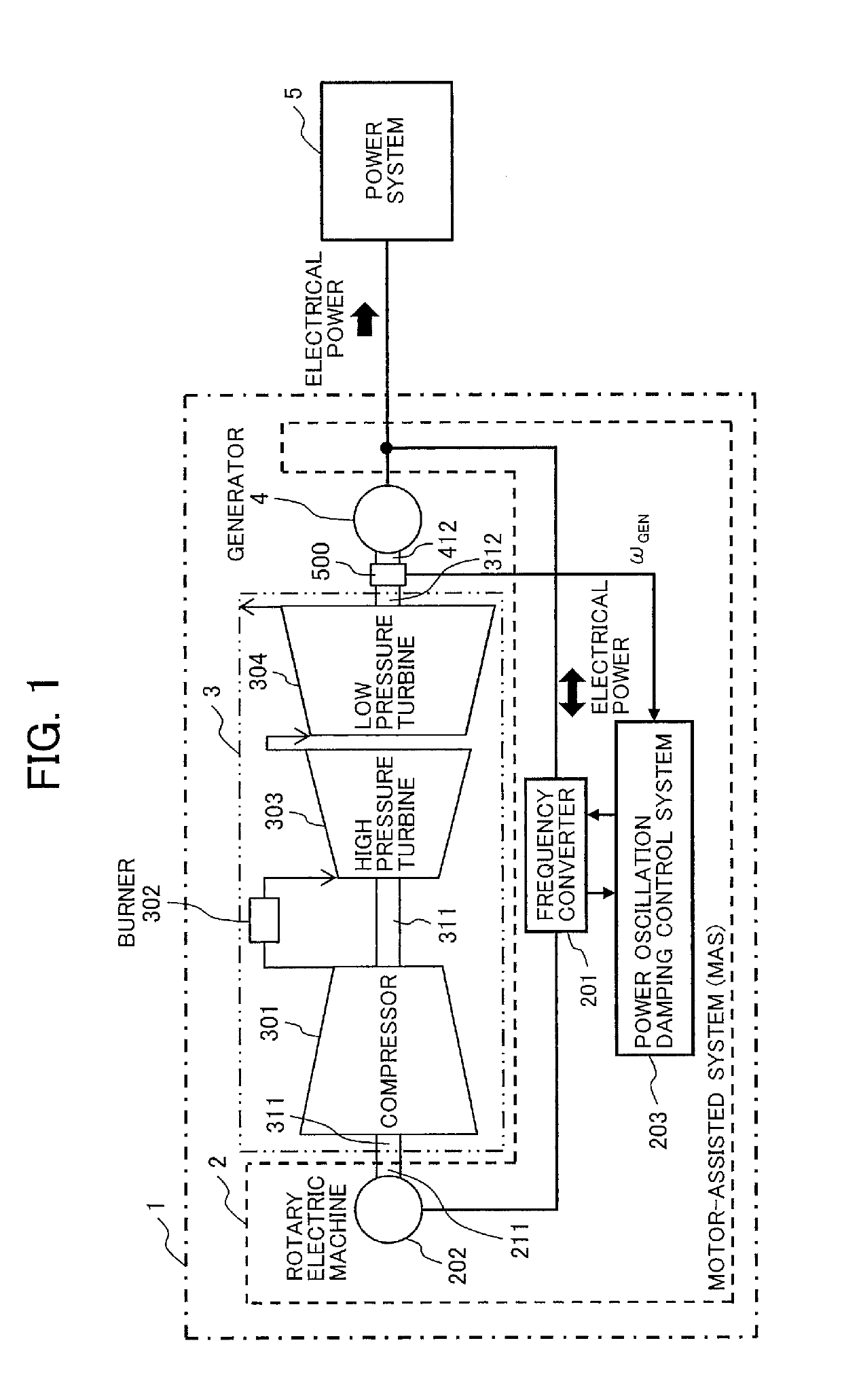
[0020]FIG. 1 illustrates an outline of a gas turbine power generation system as Example 1 according to the present invention.

[0021]The gas turbine power generation system [1] has a motor-assisted system (MAS) [2] to adjust an electric power for a power system [5] by a rotary electric machine [202] consuming or generating an electric power, a dual-shaft gas turbine [3] and a generator [4], which outputs an electric power to the power system [5], rotating by the dual-shaft gas turbine [3].

[0022]The dual-shaft gas turbine [3] has a compressor [301], a burner [302] to make a high-temperature and high-pressure gas with burning a fuel mixing with an air compressed by the compressor [301], a high pressure turbine [303] rotating by the high-temperature and high-pressure gas, a first rotating shaft [311] connecting mechanically the high pressure turbine [303] to the compressor [301] and a low pressure turbine [304], which has a second rotating shaft [312] coupling with a rotating shaft [412]...

example 2

[0052]FIG. 5 illustrates a flowchart showing processes of the power oscillation damping control system in Example 2 according to the present invention for suppression of a local power oscillation (e.g. 1.0 Hz). Additionally, a system configuration of this Example 2 is same as that of the Example 1 shown by FIGS. 1-3. Components which have the same operation as shown in the Example 1 are represented with the same numbers and so the detailed explanation of those components is skipped here. Differences between the flowcharts shown in FIGS. 4 and 5 are mainly explained, as follows.

[0053]The differences between the power oscillation damping control system of the Example 1 shown in FIG. 4 and that of the Example 2 shown in FIG. 5 are a change in the input of the operation mode in step [203_e2] and a calculation approach of the power of the motor-assisted system [2].

[0054]The power system [5] can be represented by an equivalent resistance R and a reactance X, and due to the change in activ...

example 3

[0057]FIG. 6 illustrates a flowchart showing processes of the power oscillation damping control system in Example 3 according to the present invention for suppression of an inter-system power oscillation. Additionally, a system configuration of this embodiment is same as that of the Example 1 shown by FIGS. 1-3. Components which have the same operation as shown in the Example 1 are represented with the same numbers and so the detailed explanation of those components is skipped here. Differences between the flowcharts shown in FIGS. 4 and 6 are mainly explained, as follows.

[0058]The differences between the power oscillation damping control system of the Example 1 shown in FIG. 4 and that of the Example 3 shown in FIG. 6 is a calculation approach of the powers of the motor-assisted system [2] in step [203_e3] for setting power factor. If the location of the gas turbine power generation system [1] in the power system influences an inter-system power flow, by setting a power factor, bot...


PUM


Abstract

A gas turbine power generation system having an improved function to stabilize the power system is disclosed. The gas turbine power generation system has a dual-shaft gas turbine, an electric generator mechanically connected to a low pressure turbine of the dual-shaft gas turbine and electrically connected to an electric power system, a rotary electric machine mechanically connected to a high pressure turbine through a compressor of the dual-shaft gas turbine and electrically connected to the electric power system, wherein a power oscillation is suppressed by operation of the rotary electric machine as a motor or as a generator.

Description

TECHNICAL FIELD[0001]The present invention relates to a gas turbine power generation system and a control system used in the gas turbine power generation system, which contribute stability of an electric power system.BACKGROUND ART[0002]Nowadays, distributed power supply systems provided in areas near regions consuming electric powers are increased. The distributed power supply systems are a power generation system from a renewable energy resource such as solar power or wind power and a gas turbine power generation system, etc.[0003]The gas turbine power generation system has a small size and it is operated in high efficiency. A related prior art is disclosed by WO2014 / 020772A1 (Patent Literature 1). The Patent Literature 1 describes that a dual-shaft gas turbine power generation system includes an electric motor connected to a shaft of a compressor and a frequency converter, which drives the motor, connected between the motor and a synchronous power generator connected to a shaft o...

Claims


Application Information

Patent Timeline
Patent Type & Authority Patents(United States)
IPC IPC(8): H02P9/00F02C3/10F01D15/10H02P9/04H02P101/25
CPCH02P9/006F01D15/10F02C3/10H02P9/04Y02E20/14F05D2220/76F05D2240/60F05D2260/15H02P2101/25F05D2220/32
Inventor THET, AUNG KOHINO, NORIAKIKUSUMI, NAOHIROSHIRAISHI, TOMOFUMIYOSHIMURA, MASATOSHI
Owner HITACHI LTD
Why Eureka
Try Eureka