Method for continuous thermal hydrolysis with recirculation of recovered steam

a thermal hydrolysis and steam recovery technology, applied in the direction of specific water treatment objectives, water treatment parameter control, waste based fuel, etc., can solve the problems of premature wear and tear, difficult management, and difficult degradation of certain organic compounds by biological means, and achieve non-negligible economic advantages, easy digestibility within the digester, and low cost

Active Publication Date: 2019-04-23
CAMBI TECH AS
View PDF11 Cites 0 Cited by
  • Summary
  • Abstract
  • Description
  • Claims
  • Application Information

AI Technical Summary

Benefits of technology

[0040]The uniform mixture, constituted by the first and second uniform mixtures, carried out prior to the thermal hydrolysis, enables the steam to get condensed in the sludge at the dynamic injector-mixers and thus to heat the sludge. This uniform mixture is then conveyed towards the reactor in which its flow can be as close as possible to the plug flow. Taking the form of a uniform mono-phase liquid phase, it enters the reactor at a uniform temperature, a temperature at which the thermal hydrolysis of the poorly biodegradable compounds can be done in an efficient and optimized way.
[0095]It is thus possible to lower the temperature of the sludge and / or modify its concentration in order to make them compatible (in terms of temperature and / or concentration) with the biological phenomena involved as the case may be in the digestion that follows.

Problems solved by technology

However, certain organic compounds are more difficult to degrade by biological means than others and it is known that pre-treatment by thermal hydrolysis accelerates the process of biological degradation.
Such batch treatment methods have the drawbacks of making it necessary to manage the treatment cycles for treating the different batches of sludge that have to be treated and requiring repetitive operation of certain apparatuses, such as the opening / closing of valves for example which may lead to premature wear and tear.
This technique however uses exchangers on non-hydrolyzed concentrated sludge with a dry solids content of more than 10%, which can be difficult to manage in practice, entailing constraints for the user since it requires periods of stoppage for maintenance and cleaning.
), and experience shows that this factor causes this pump to have a short service life.
Finally, this configuration is limited in terms of concentration of the sludge to be treated since it cannot be used to treat sludge having a dry content of over 20%.
However, although the treatment of sludge by thermal hydrolysis has been greatly improved over other methods existing in the market, it still has certain limits.
First of all, if the viscosity of the sludge to be hydrolyzed, introduced into the reactor, is too high, it may prove to be difficult to inject steam into this sludge.
Beyond certain dry content levels, the thermal hydrolysis could prove to be non-optimal, and this would limit the performance of anaerobic digestion situated downstream from the thermal hydrolysis.
Indeed, if this step is not done properly, the performance of the method of thermal hydrolysis can be considerably impaired, in terms of chemical reaction as well as in economic terms, since the quantity of steam that has to be used then becomes greater.
The methods of thermal hydrolysis on dewatered sludge therefore come up against the difficulty of having to inject steam into the sludge efficiently and, as a corollary, the difficulty of mixing them when this sludge is too viscous.
Since sludge is viscous by nature, the greater its dry content, the more difficult it will be for the steam to be injected into the sludge, get mixed with the sludge and yield its energy by condensation to prompt the thermal hydrolysis of the poorly biodegradable compounds.
However, in both the continuous methods and the batch-treatment methods of the prior art, the sludge cannot be efficiently hydrolyzed in practice, at least in the industrial-level transposition that is made of the techniques described and claimed in the patent documents cited here above, once their dry content is greater than 20%.
This propensity therefore lowers the performance of the thermal hydrolysis reactor.
It will be noted however that, to the knowledge of the present Applicant, no industrial-scale device using such dynamic or static mixers for the treatment of sludge has been applied as yet to commercially used installations.

Method used


Image

  • Method for continuous thermal hydrolysis with recirculation of recovered steam
  • Method for continuous thermal hydrolysis with recirculation of recovered steam
  • Method for continuous thermal hydrolysis with recirculation of recovered steam

Examples


first embodiment

6.2. Example of a First Embodiment

Heat Exchanger

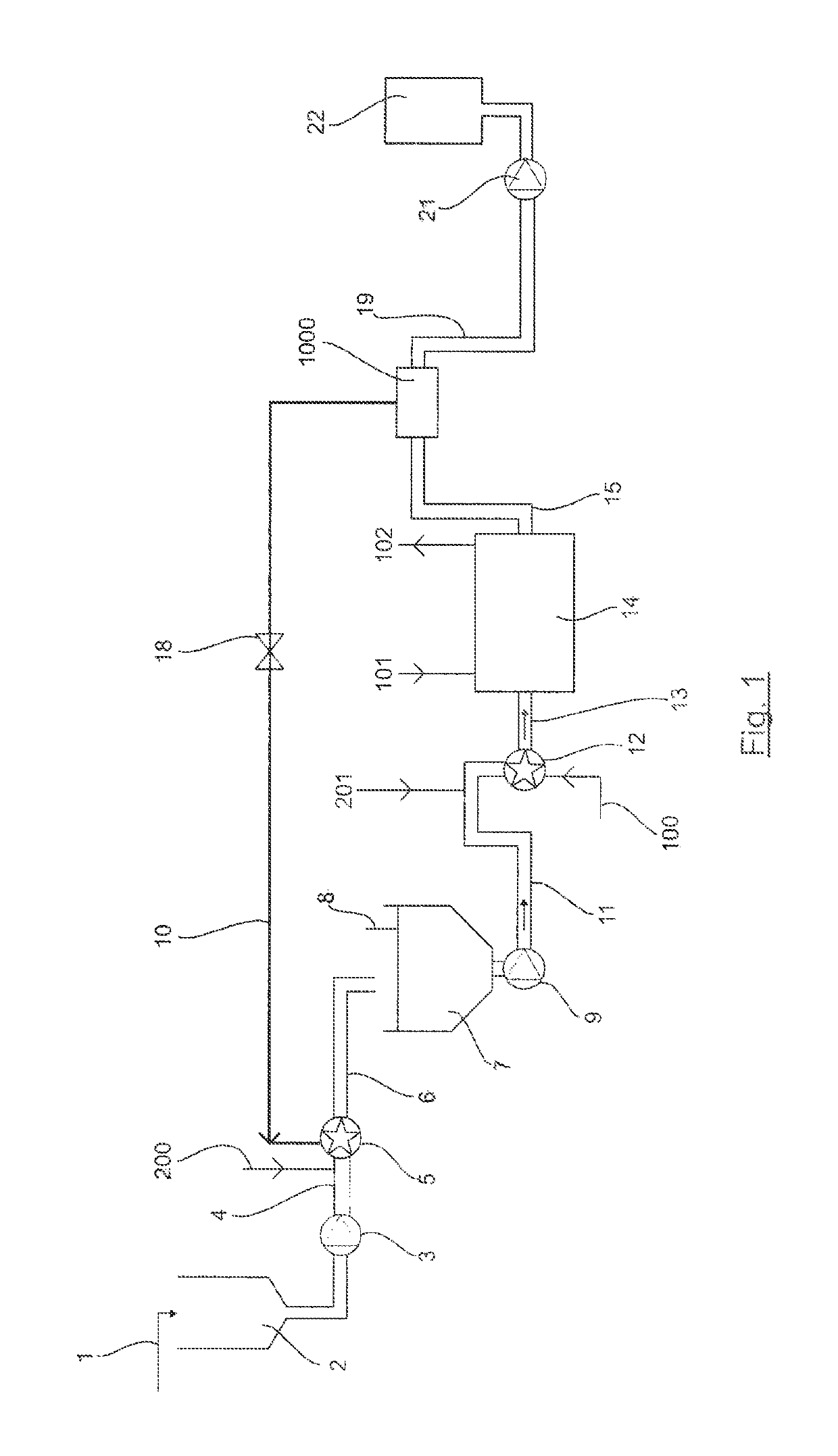
[0142]Referring to FIG. 6, a schematic description is provided of a device according to a first embodiment of the invention.

[0143]Only the differences between the device generally illustrated in FIG. 1 and the device according to this first embodiment illustrated in FIG. 6 are described.

[0144]According to this first embodiment, the means 1000 for producing recovered steam comprise a heat exchanger 90.

[0145]This heat exchanger 90 comprises a first inlet 901 into which there opens the pipe 15 through which the hydrolyzed sludge coming from the thermal hydrolysis reactor 14 is conveyed into this exchanger 90. It comprises a second inlet 902 to which there are connected means for leading in water, herein comprising a pipe 91. It also comprises a recovered steam outlet 903 to which there is connected the recovered steam injection pipe 10 which opens into the primary dynamic injector-mixer 5. This heat exchanger 90 also comprises an outlet 9...

second embodiment

6.3. Example of a Second Embodiment

Flash Reactor

[0162]Referring to FIG. 11, a schematic description is provided of a device according to a second embodiment of the invention.

[0163]Only the differences between the device generally illustrated in FIG. 1 and the device according to this second embodiment illustrated in FIG. 11 are described.

[0164]In this embodiment, the recovered steam production means comprise a flash reactor 16.

[0165]The pressure and the temperature of the hydrolyzed sludge when exits the reactor 14 are sharply and rapidly lowered within the flash reactor 16 in order to produce flash steam, the pressure of which will preferably range from 1 to 10 bar A and the temperature of which will preferably range from 100 to 180° C.

[0166]The flash steam thus produced, which constitutes the recovered steam directly produced from the heat of the hydrolyzed sludge, is conveyed into the primary dynamic injector-mixer 5 via the pipe 10 serving as a means for injecting recovered stea...


PUM

PropertyMeasurementUnit
pressureaaaaaaaaaa
temperatureaaaaaaaaaa

Abstract

The invention pertains to a method for the continuous thermal hydrolysis of sludge to be treated, containing organic matter, said method comprising the steps of simultaneously carrying out the injection of recovered steam into said sludge and mixing said sludge with said recovered steam by means of a primary dynamic injector-mixer so as to obtain a primary uniform mixture; simultaneously carrying out the injection of fresh steam into said primary uniform mixture and mixing said primary uniform mixture with said fresh steam by means of a secondary dynamic injector-mixer so as to obtain a secondary uniform mixture of sludge; conveying said secondary uniform mixture towards a tube reactor under pressure and prompting an essentially plug-type flow of this secondary uniform mixture into said reactor for a residence time that is sufficient and at a temperature that is sufficient to enable the thermal hydrolysis of the organic matter present in this secondary uniform mixture; producing said recovery steam within means for the production of recovered steam from said secondary uniform mixture obtained at exit from said tubular reactor; cooling said secondary uniform mixture when it exits said means for producing recovery steam to a temperature enabling the subsequent digestion of the hydrolyzed organic matter that it contains.

Description

[0001]This application is a U.S. National Stage Application of PCT Application No. PCT / EP2014 / 066254, with an international filing date of 29 Jul. 2014. Applicant claims priority based on French Patent Application Nos. 1358591 filed 6 Sep. 2013. The subject matter of these applications is incorporated herein.1. FIELD OF THE INVENTION[0002]The present invention pertains to a method and a device for the continuous thermal hydrolysis of sludge containing organic matter, which may or may not be mixed with other wastes containing organic matter. This sludge or these wastes can for example be derived from the treatment of domestic wastewater (digested or non-digested cleansing sludge, fats derived from pre-treatment), or from the treatment of industrial wastewater (for example wastewater from the food processing industry, slaughterhouses, molasses, etc.), or home refuse type wastes containing organic matter or derived from discharged matter, grease tanks, etc. The term “sludge” shall be u...

Claims


Application Information

Patent Timeline
Patent Type & Authority Patents(United States)
IPC IPC(8): C02F1/02C02F11/12C02F11/18C02F103/32
CPCC02F1/025C02F11/12C02F11/18C02F2103/32C02F2209/001C02F2209/02C02F2209/03C02F2209/44C02F2303/10Y02W10/30Y02E50/30
Inventor CHAUZY, JULIENCRAMPON, CEDRICAUPETIT, THIERRYGILBERT, ANDREW B.
Owner CAMBI TECH AS
Why Eureka
Try Eureka