
Enhanced heat recovery in paraxylene plant

a technology of enhanced heat recovery and paraxylene, which is applied in the direction of sustainable manufacturing/processing, separation processes, bulk chemical production, etc., can solve the problems of increasing the cost of fractionation equipment, and affecting the efficiency of production

Active Publication Date: 2019-04-23
INEOS US CHEM CO
View PDF23 Cites 1 Cited by
  • Summary
  • Abstract
  • Description
  • Claims
  • Application Information

AI Technical Summary

Benefits of technology

This approach enhances energy efficiency by recovering high-quality heat that can be used elsewhere in the plant, reducing energy wastage and operational costs, while maintaining separation efficiency without increasing tower pressure.

Problems solved by technology

Crystallization is much less sensitive to impurities in the fractionation product stream than selective adsorption, where these impurities can lead to manufacturing difficulties.
If the fractionation tower operates at close to ambient conditions, the heat removed in the overhead condenser is often too low in temperature or thermodynamic quality to be useful.
However raising the tower pressure increases the cost of the fractionation equipment and lowers the separation efficiency.
One disadvantage of side condensers is that the heat removed by condensing the tower side condenser product contains low molecular weight gases.
There are problems associated with the flashing of these low molecular weight gases if side condensers are employed.

Method used


Image

  • Enhanced heat recovery in paraxylene plant

Examples


example 1

Increasing Vapor Sidedraw Flow Rate on Duties, Temperatures, and Concentrations

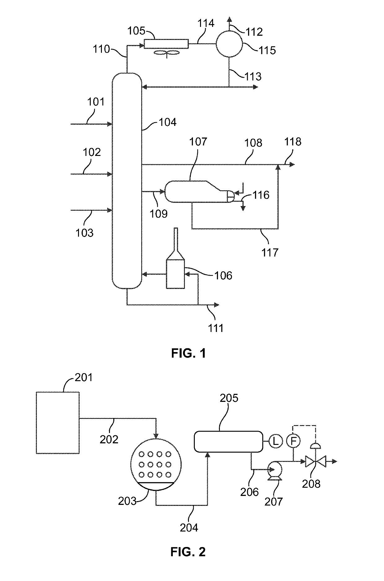
[0021]This example shows the effect of increasing the vapor sidedraw flow rate on condenser and reboiler duties, the condensing temperature, and the toluene concentration in the liquid sidedraw. Results are shown in Table 1 below. For the base simulation, the condenser and reboiler duties of the xylene recovery column are about 34.6 and 55.9 Mmkcal / hr, respectively. Simulation numbers 1, 2, and 3 use increasing vapor flow rates for the sidedraw condenser. As the vapor flow rate increases, the vapor sidedraw condenser duty increases, which provides useful work. In addition, the column overhead condenser duty decreases, saving energy. As the vapor flow rate increases, the column reboiler duty and the toluene concentration increase only slightly. Vapor does not go to the top of the column where the toluene is removed. There are limits to how much heat can be removed. It was surprising that a large quantity o...

example 2

of Lowering Vapor Sidedraw Removal Location on Condensing Temperature, Reboiler Duty, and Sidedraw Composition

[0023]This example shows the effect of the location of the sidedraw on vapor sidedraw temperature, column reboiler duty, and liquid sidedraw composition. The total number column stages is kept constant in each simulation. Results are shown in Table 2 below. These results start at two stages below where feed stream 102 enters the column. It was very surprising that the concentration of low molecular weight gases in the vapor phase was so low only two stages below where feed stream 102 enters the column. When the sidedraw is located further down in the column (i.e., at more stages below the sidedraw and the feed stream coming from the high temperature separator), the temperature increases, which improves the quality of the heat available. However, this also increases the column reboiler duty because removing vapor from further down the column provides fewer stages to perform t...


PUM

PropertyMeasurementUnit
temperatureaaaaaaaaaa

Abstract

Processes and apparatuses for enhanced heat recover} / in a paraxylene manufacturing plant use a side condenser to recover high quality heat. By placing the side condenser below the location of a feed stream comprising low molecular weight gases, the heat recovered is free of such non-condensable gases. Such gases are undesirable when using the condensed vapor in other applications.

Description

CROSS-REFERENCE TO RELATED APPLICATION[0001]This application claims priority to U.S. Provisional Application No. 61 / 917,061, filed Dec. 17, 2013, which is hereby incorporated by reference in its entirety.FIELD[0002]This disclosure relates to processes and apparatuses for enhanced heat recovery during the manufacture of paraxylene. Such processes and apparatuses include a side condenser located at a position such that the liquid formed from the condensed vapor is free of non-condensable low molecular weight gases.BACKGROUND[0003]Paraxylene is used in the manufacture of polyester which is useful as fibers and polymeric resins. Paraxylene can be manufactured from several feedstocks, the most significant today being reformate produced from naphtha reforming. The two primary processes used to manufacture paraxylene use crystallization or selective adsorption.[0004]Both types of paraxylene manufacturing plants employ heat in the reboiler(s) of a distillation or fractionation tower(s) to s...

Claims


Application Information

Patent Timeline
Patent Type & Authority Patents(United States)
IPC IPC(8): C07C7/04B01D9/00B01D3/32B01D3/00C07C7/00C07C7/14
CPCC07C7/005B01D3/007B01D3/322B01D9/0031C07C7/04C07C7/14C07C15/08Y02P20/51Y02P20/57Y02P70/34Y02P20/10Y02P20/50Y02P70/10F01K17/06
Inventor COLLING, CRAIG
Owner INEOS US CHEM CO
Learn More