Catalytic wall-flow filter having a membrane

a technology of membrane and filter, which is applied in the field of catalytic wall-flow filter, can solve the problems of significant temperature gradient and reduce the longevity of the device, and achieve the effects of preventing the build-up of back pressure, reducing the longevity of the device, and preventing the build-up of soo

Active Publication Date: 2019-04-30
JOHNSON MATTHEY PLC
View PDF28 Cites 0 Cited by
  • Summary
  • Abstract
  • Description
  • Claims
  • Application Information

AI Technical Summary

Benefits of technology

[0029]The present inventors have found that by providing the microporous membranes as discussed herein, it is possible to direct the soot deposition locations. Microporous membranes are coatings which have pores sized to be smaller than the soot particles being recovered. This means that the membrane permits the through-flow of gases for treatment, but prevents the build-up of soot within the larger pores of the porous substrate in areas protected by the membrane. The provision of a microporous membrane therefore prevents the build-up of back pressure in those regions, in use.
[0102]The inventors have found that when the extra on-wall coating is increased in the rear portion beyond the level required to prevent soot deposition, the coating can have a direct effect on increasing the backpressure in the rear portion of the first channels. That is, the thickness of the coating can provide sufficient back-pressure to deter the deposition of soot in the rear portion. In particular, the coating should be sufficient such that the soot loaded back pressure is 20% higher in the rear than the front by virtue of the increased coating thickness in the rear section. This reduces soot deposition towards the rear of the monolith and helps to prevent undue heat build-up in this portion during regeneration.

Problems solved by technology

Typically in conventional filters, more soot accumulates at the back, leading to a significant temperature gradient and reducing the longevity of the device.

Method used


Image

  • Catalytic wall-flow filter having a membrane
  • Catalytic wall-flow filter having a membrane
  • Catalytic wall-flow filter having a membrane

Examples


Embodiment Construction

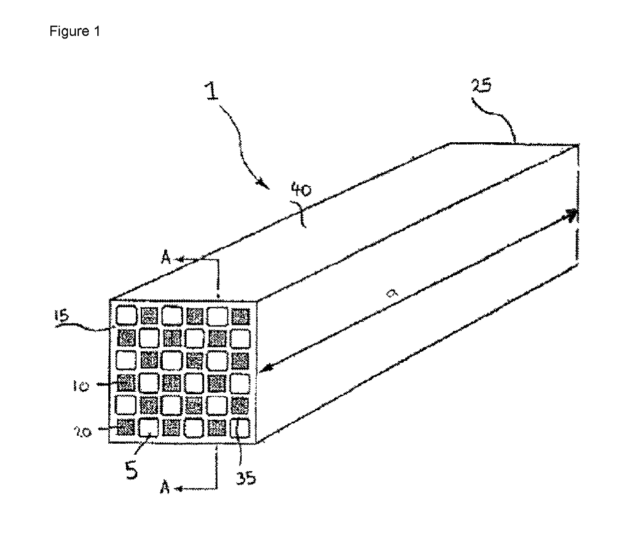
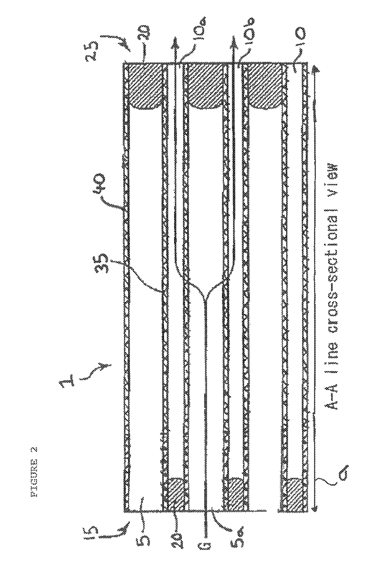
[0112]A wall flow monolith 1 according to the present invention is shown in FIG. 1 and FIG. 2. It includes a large number of channels arranged in parallel with each other in the longitudinal direction (shown by a double-sided arrow “a” in FIG. 1A) of the monolith 1. The large number of channels includes a first subset of channels 5 and a second subset of channels 10.

[0113]The channels are depicted such that the second subset of channels 10 is narrower than the first subset of channels 5. This has been found to provide an increased ash storage capacity in the filter. However, the channels may alternatively be the same size.

[0114]The first subset of channels 5 is open at an end portion on a first end face 15 of the wall flow monolith 1 and is sealed with a sealing material 20 at an end portion on a second end face 25.

[0115]On the other hand, the second subset of channels 10 is open at an end portion on the second end face 25 of the wall flow monolith 1 and is sealed with a sealing mat...


PUM

PropertyMeasurementUnit
temperaturesaaaaaaaaaa

Abstract

The present invention relates to a catalytic wall-flow monolith for use in an emission treatment system, the monolith comprising a porous substrate and having a first face and a second face defining a longitudinal direction therebetween and first and second pluralities of channels extending in the longitudinal direction,the first plurality of channels provides a first plurality of inner surfaces and is open at the first face and closed at the second face, and the second plurality of channels is open at the second face and closed at the first face,a first catalytic material is distributed within the porous substrate,a microporous membrane is provided in the first plurality of channels on a first portion, extending in the longitudinal direction, of the first plurality of inner surfaces, andthe first portion extends from the first face for 75 to 95% of a length of the first plurality of channels.

Description

CROSS-REFERENCE TO RELATED APPLICATIONS[0001]This claims priority to U.S. Provisional Patent Application No. 62 / 185,695, filed Jun. 28, 2015, which is incorporated herein by reference.FIELD OF THE INVENTION[0002]The present invention relates to a catalytic wall-flow monolith suitable for use in an emission treatment system, such as an automobile internal combustion exhaust system. The monolith provides an effective method of remediating engine exhaust streams.BACKGROUND OF THE INVENTION[0003]Emissions from internal combustion engines, including diesel engines, are limited by legislation put in place by governments worldwide. Manufacturers are seeking to meet these legislated requirements through a combination of engine design and exhaust gas after-treatment. The exhaust systems used to carry out exhaust gas after-treatment commonly comprise a series of catalysts and / or filters that are designed to carry out certain reactions that reduce the proportion of exhaust gas species limited ...

Claims


Application Information

Patent Timeline
Patent Type & Authority Patents(United States)
IPC IPC(8): B01J29/70F01N3/20B01J29/064F01N3/035F01N3/022B01D46/24B01J29/50B01J35/04B01J37/02B01J35/00B01D53/94B01J23/10B01J29/076B01J29/85B01J29/84B01J29/83B01J29/76B01J29/74B01J29/72
CPCB01J29/7015B01D46/2474B01D53/944B01D53/9418B01D53/9454B01J23/10B01J29/064B01J29/076B01J29/50B01J29/70B01J29/72B01J29/743B01J29/763B01J29/83B01J29/84B01J29/85B01J35/0006B01J35/04B01J37/0201B01J37/0244B01J37/0246F01N3/0222F01N3/035F01N3/2066B01D46/2455Y02T10/24B01D2255/502B01D2255/504B01D2255/9155B01D2255/9202B01D2258/012B01D2325/10B01J2229/186F01N2240/40F01N2250/02F01N2330/06F01N2330/32F01N2330/48F01N2330/60F01N2510/0682Y02T10/12B01D46/2484B01D46/2476F01N3/2828F01N3/28B01D53/94B01D46/24F01N3/022F01N3/023
Inventor CHANDLER, GUY RICHARDPHILLIPS, PAUL RICHARD
Owner JOHNSON MATTHEY PLC
Why Eureka
Try Eureka