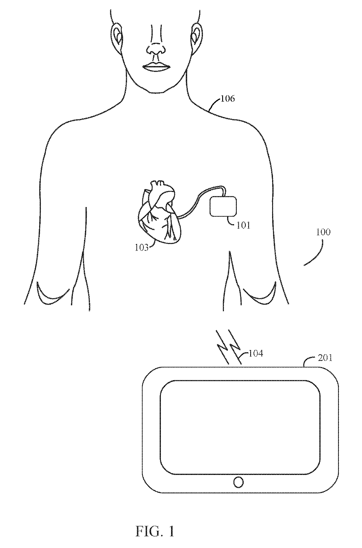
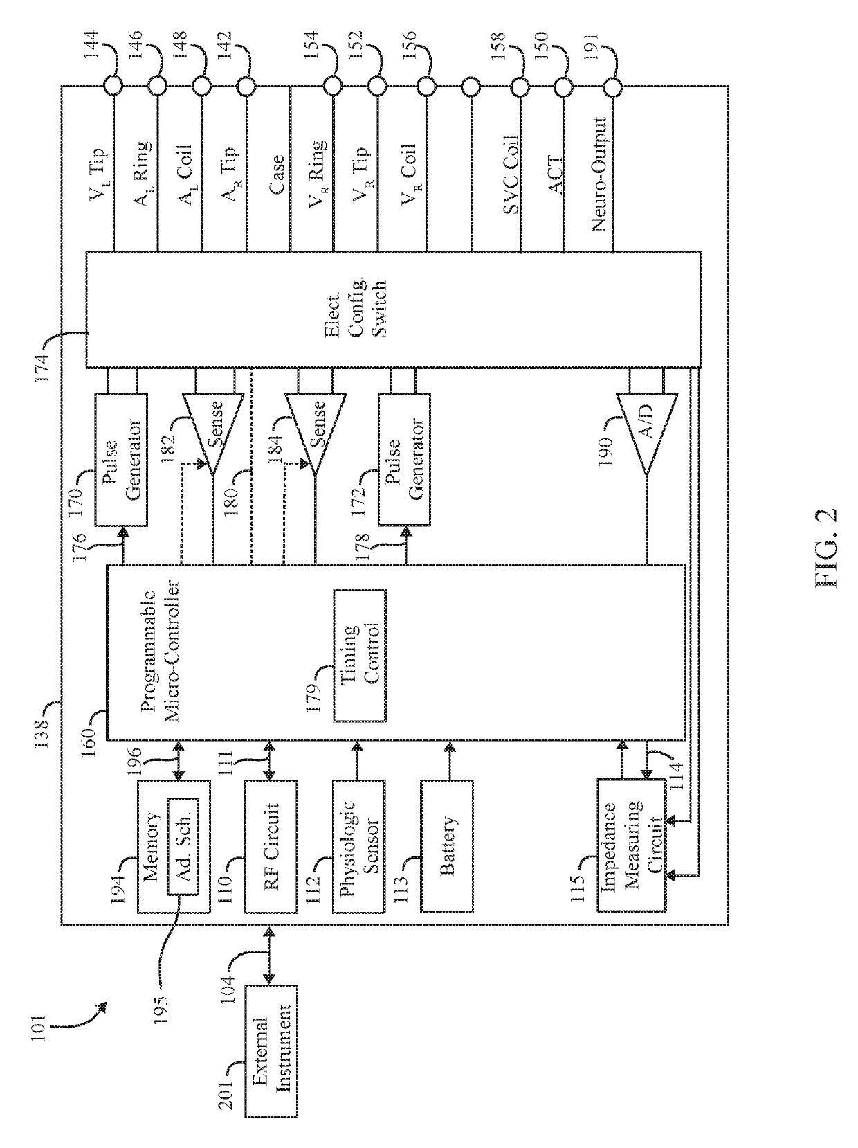
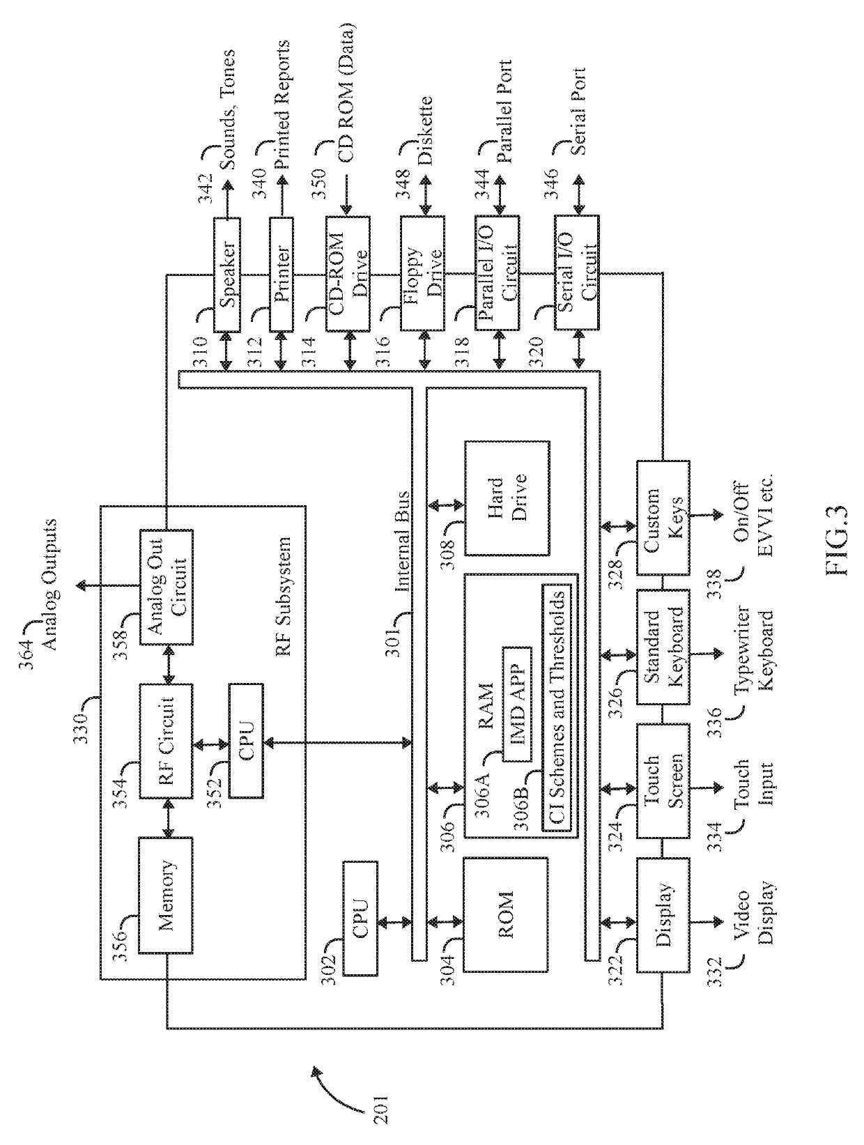
Managing dynamic connection intervals for implantable and external devices

a dynamic connection and external device technology, applied in power management, high-level techniques, therapy, etc., can solve the problems of increasing the frequency of monitoring period of external instruments, and increasing the cost of monitoring

Active Publication Date: 2019-04-30
PACESETTER INC
View PDF9 Cites 7 Cited by
  • Summary
  • Abstract
  • Description
  • Claims
  • Application Information

AI Technical Summary

Problems solved by technology

However, the current drain expended by the IMD to broadcast the advertisement notices can be too high where battery life is a concern, particularly in smaller devices that have limited space for batteries.
However, many external instruments have built in constraints related to how long the external instrument will monitor for advertisement notices for usability and power consumption purposes.
If an advertisement notice is not received by the external instrument within a predetermined number of monitoring periods, the external instrument may decrease the frequency of the monitoring period.
When multiple unsuccessful monitoring periods occur, the battery of the external instrument is undesirably drained.
The power consumption of the battery of an IMD is a major design constraint.
There is a limited total amount of drain allowable for active device communications with EIs when the BLE link is active.
However, the power consumption during the connection interval 1 will be higher during the session in which the EI is connected.
Conversely, if the BLE link utilizes connection interval 2, such as a 100 ms per packet exchange, a limited data throughput bandwidth is likely due to limited data being exchanged during a fixed time period.
In accordance with the foregoing, conventional BLE telemetry protocols cause an undue drain on the IMD battery.

Method used


Image

  • Managing dynamic connection intervals for implantable and external devices
  • Managing dynamic connection intervals for implantable and external devices
  • Managing dynamic connection intervals for implantable and external devices

Examples


Embodiment Construction

[0026]It will be readily understood that the components of the embodiments as generally described and illustrated in the figures herein, may be arranged and designed in a wide variety of different configurations in addition to the described example embodiments. Thus, the following more detailed description of the example embodiments, as represented in the figures, is not intended to limit the scope of the embodiments as claimed, but is merely representative of example embodiments.

[0027]Reference throughout this specification to “one embodiment” or “an embodiment” (or the like) means that a particular feature, structure, or characteristic described in connection with the embodiment is included in at least one embodiment. Thus, appearances of the phrases “in one embodiment” or “in an embodiment” or the like in various places throughout this specification are not necessarily all referring to the same embodiment.

[0028]A connection interval scheme may be defined based on various connecti...


PUM


Abstract

A method, system and external instrument are provided. The method initiates a communication link between an external instrument (EI) and an implantable medical device (IMD), established a first connection interval for conveying data packets between the EI and IMD and monitors a connection criteria that includes at least one of a data throughput requirement. A battery indicator or link condition of the communications link is between the IMD and EI. The method further changes from the first connection interval to a second connection interval based on the connection criteria.

Description

PRIORITY CLAIM[0001]The present application relates to and claims priority from U.S. provisional application Ser. No. 62 / 427,216, filed Nov. 29, 2016, entitled “MANAGING DYNAMIC CONNECTION INTERVALS FOR IMPLANTABLE AND EXTERNAL DEVICES,” which is hereby expressly incorporated by reference in its entirety to provide continuity of disclosure.BACKGROUND[0002]Embodiments of the present disclosure generally relate to systems and methods for establishing a communication link between devices, and more particularly to managing dynamic connection intervals for BLE utilized to establish communication links between implantable medical devices and external instruments.[0003]An implantable medical device (IMD) is a medical device to be implantable within a patient anatomy. Some IMDs employ one or more leads with electrodes that either receive or deliver voltage, current or other electromagnetic pulses from or to an organ or tissue for diagnostic or therapeutic purposes. Other IMDs operate withou...

Claims


Application Information

Patent Timeline
Patent Type & Authority Patents(United States)
IPC IPC(8): H04W4/80H04W76/20H04W76/10H04W52/02H04L29/06A61N1/372
CPCH04W76/10A61N1/37247A61N1/37276H04L69/28H04W4/80H04W52/0216H04W76/20A61N1/37223Y02D70/26H04W52/0254H04W52/0277Y02D70/00Y02D70/10Y02D70/14Y02D70/144Y02D70/164Y02D70/20H04W84/18Y02D30/70
Inventor WU, YONGJIANYOUNG, CHAO-WENYANG, JUNPEI, XINGSHAHANDEH, REZA
Owner PACESETTER INC
Why Eureka
Try Eureka