Standard cell circuits employing voltage rails electrically coupled to metal shunts for reducing or avoiding increases in voltage drop

a technology of voltage rails and voltage rails, which is applied in the direction of electrical equipment, semiconductor devices, semiconductor/solid-state device details, etc., can solve the problems of increasing voltage drop, reducing the height of a conventional standard cell circuit may face limitations, and the width of a conventional standard cell circuit cannot continue to scale down due to gate pitch limitations, etc., to reduce or avoid the effect of increasing the conductive area reducing the resistance of the voltage rails

Active Publication Date: 2019-05-07
QUALCOMM INC
View PDF17 Cites 2 Cited by
  • Summary
  • Abstract
  • Description
  • Claims
  • Application Information

AI Technical Summary

Benefits of technology

[0005]Aspects disclosed herein include standard cell circuits employing voltage rails electrically coupled to metal shunts for reducing or avoiding increases in voltage drop. In particular, standard cell circuits described herein include metal lines disposed with a metal pitch, such that the number of metal lines allows some metal lines to be dedicated to electrically coupling voltage rails to metal shunts to increase the conductive area of the voltage rails. The increased conductive area reduces the resistance of the voltage rails, which reduces the voltage drop across the voltage rails. In this manner, the voltage rails can have a relatively smaller width while reducing or avoiding increases in voltage drop across the voltage rails. In one exemplary aspect, a standard cell circuit is provided in a circuit layout that employs active devices that include corresponding gates disposed with a gate pitch. A first voltage rail having a line width is disposed in a first metal layer, and a second voltage rail having substantially the same line width as the first voltage rail is disposed in the first metal layer. Employing the first and second voltage rails having substantially the same line width reduces the height of the standard cell circuit compared to conventional standard cell circuits. Metal lines are disposed in a second metal layer with a metal pitch less than the gate pitch, such that the number of metal lines exceeds the number of gates. In this manner, additional metal lines can be provided that can be dedicated to coupling the voltage rails to metal shunts disposed in a third metal layer to reduce the resistance of the narrower width voltage rails, while other metal lines can be dedicated to interconnecting the gates of the active devices. Electrically coupling the first and second voltage rails to the metal shunts increases the conductive area of each voltage rail, which reduces a corresponding resistance. The reduced resistance corresponds to a reduced voltage drop (i.e., current-resistance (IR) drop) across each voltage rail. Thus, the standard cell circuit achieves a reduced area compared to conventional standard cell circuits by way of the narrower voltage rails, while also reducing or avoiding increases in voltage drop corresponding to the narrower voltage rails.

Problems solved by technology

However, as the technology node size scales down to ten (10) nm and below for example, the width of a conventional standard cell circuit cannot continue to scale down due to gate pitch limitations.
Additionally, reducing the height of a conventional standard cell circuit may face limitations due to voltage requirements.
However, scaling down voltage rails increases rail resistances, thus increasing a voltage drop (i.e., current-resistance (IR) drop) across the voltage rails.
Increased voltage drop reduces the voltage available from the voltage rails for devices in a conventional standard cell circuit, which may cause erroneous operation of the devices.

Method used


Image

  • Standard cell circuits employing voltage rails electrically coupled to metal shunts for reducing or avoiding increases in voltage drop
  • Standard cell circuits employing voltage rails electrically coupled to metal shunts for reducing or avoiding increases in voltage drop
  • Standard cell circuits employing voltage rails electrically coupled to metal shunts for reducing or avoiding increases in voltage drop

Examples


Embodiment Construction

[0018]With reference now to the drawing figures, several exemplary aspects of the present disclosure are described. The word “exemplary” is used herein to mean “serving as an example, instance, or illustration.” Any aspect described herein as “exemplary” is not necessarily to be construed as preferred or advantageous over other aspects.

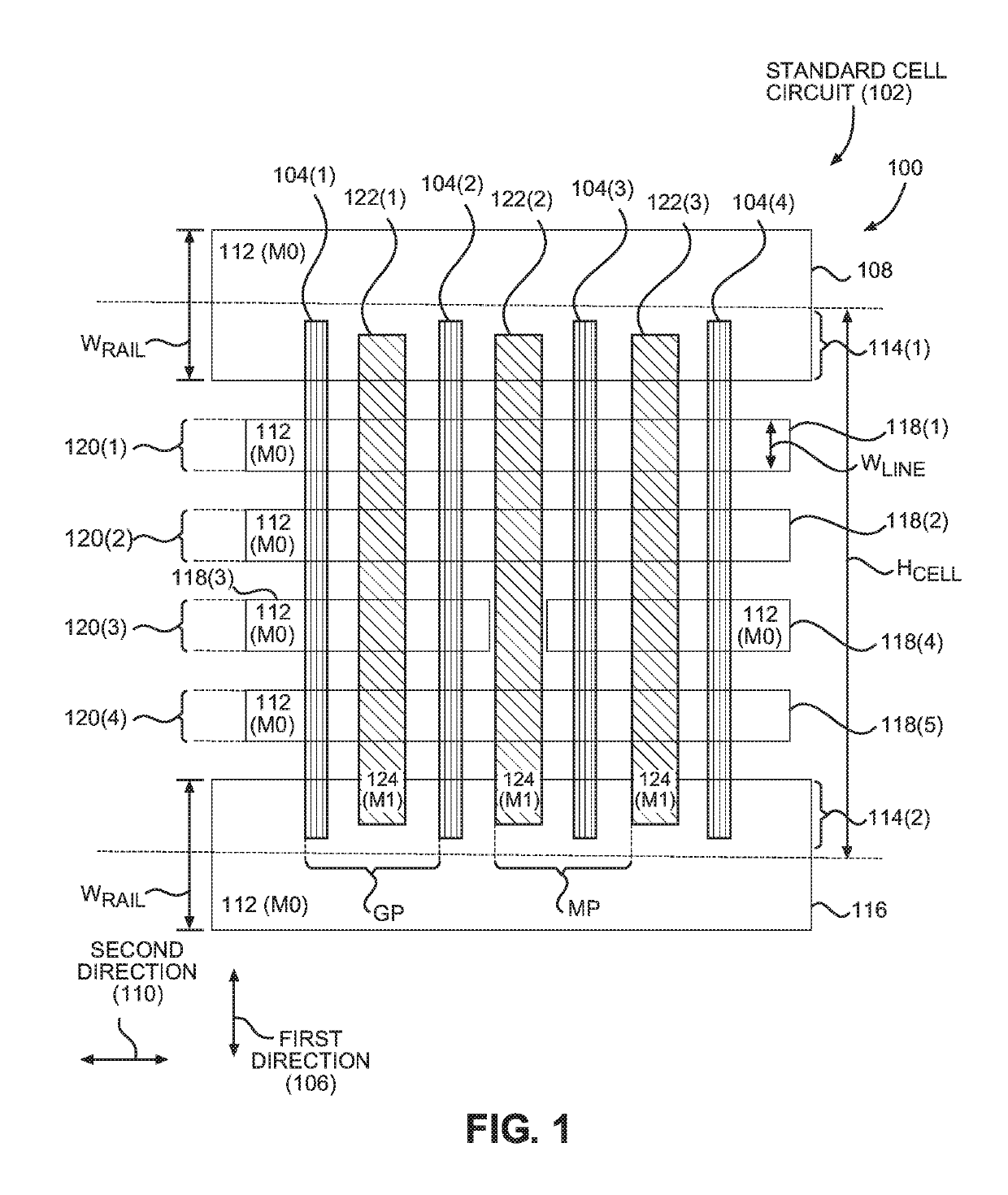
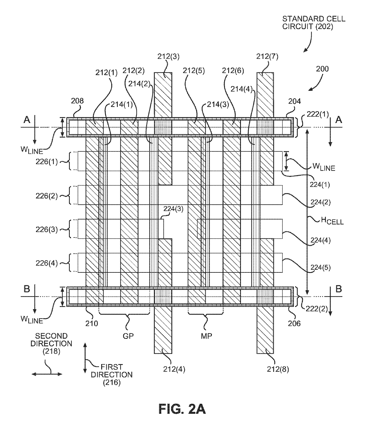
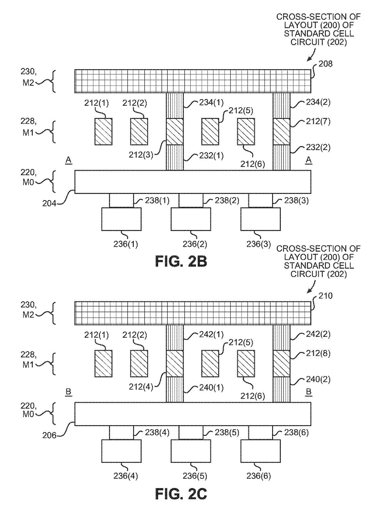
[0019]Aspects disclosed herein include standard cell circuits employing voltage rails electrically coupled to metal shunts for reducing or avoiding increases in voltage drop. In particular, standard cell circuits described herein include metal lines disposed with a metal pitch, such that the number of metal lines allows some metal lines to be dedicated to electrically coupling voltage rails to metal shunts to increase the conductive area of the voltage rails. The increased conductive area reduces the resistance of the voltage rails, which reduces the voltage drop across the voltage rails. In this manner, the voltage rails can have a relatively smaller...


PUM


Abstract

Standard cell circuits employing voltage rails electrically coupled to metal shunts for reducing or avoiding increases in voltage drop are disclosed. In one aspect, a standard cell circuit is provided that employs active devices that include corresponding gates disposed with a gate pitch. First and second voltage rails having a line width are disposed in a first metal layer. Employing the first and second voltage rails having substantially a same line width reduces the height of the standard cell circuit as compared to conventional standard cell circuits. Metal lines are disposed in a second metal layer with a metal pitch less than the gate pitch such that the number of metal lines exceeds the number of gates. Electrically coupling the first and second voltage rails to the metal shunts increases the conductive area of each voltage rail, which reduces a voltage drop across each voltage rail.

Description

BACKGROUNDI. Field of the Disclosure[0001]The technology of the disclosure relates generally to standard cell circuits, and particularly to avoiding or reducing increases in voltage drop in standard cell circuits.II. Background[0002]Processor-based computer systems can include a vast array of integrated circuits (ICs). Each IC has a complex layout design comprised of multiple IC devices. Standard cell circuits are often employed to assist in making the design of ICs less complex and more manageable. In particular, standard cell circuits provide a designer with pre-designed cells corresponding to commonly used IC devices that conform to specific design rules of a chosen technology. As non-limiting examples, standard cell circuits may include gates, inverters, multiplexers, and adders. Using standard cell circuits enables a designer to create ICs having consistent layout designs, thereby creating a more uniform and less complex layout design across multiple ICs, as compared to custom-...

Claims


Application Information

Patent Timeline
Patent Type & Authority Patents(United States)
IPC IPC(8): H01L27/10H01L27/118H01L21/8234H01L27/02H01L23/528H01L23/538H01L23/50
CPCH01L27/11807H01L21/823475H01L23/50H01L23/5386H01L27/0207H01L23/5286H01L2027/11881H01L2027/11875
Inventor ZHU, JOHN JIANHONGXU, JEFFREY JUNHAOBADAROGLU, MUSTAFA
Owner QUALCOMM INC
Why Eureka
Try Eureka