Electrical connector

a technology of electrical connectors and connectors, applied in the direction of electrically conductive adhesive connections, coupling device connections, incorrect coupling prevention, etc., can solve the problems of signal transmission process distorted or errors, data transmission amount increases accordingly, and conventional transmission devices cannot meet the current high efficiency requirements. , to achieve the effect of reducing crosstalk and enhancing the shielding effect of grounding terminals

Active Publication Date: 2019-05-07
SPEED TECH
View PDF62 Cites 35 Cited by
  • Summary
  • Abstract
  • Description
  • Claims
  • Application Information

AI Technical Summary

Benefits of technology

[0011]The aspect of this disclosure is to design an electrical connector, in which the electrical connector includes conductive terminals forming terminal groups. The conductive terminals includes signal terminals and grounding terminals, in which each of the conductive terminals comprises a contact portion, a soldering portion, and a main portion connecting the contact portion and the soldering portion. An insulation body is fixed to each main portion of the con

Problems solved by technology

With the rapid development of technology, the amount of data transmission increases accordingly, and thus conventional transmission devices cannot meet the current high efficiency requirements.
Because transmitting signals at use the high-frequency frequency band, the two adjacent terminals are highly susceptible to mutual high-frequency noise interference, such as cross talk, impedance, propagation delay, propagation skew, and attenuation, thus causing the signal transmission process to be distorted or have errors, greatly reducing the transmission efficiency of the electrical connector.
However, contact surfaces between the metal grounding parts and the gro

Method used


Image

  • Electrical connector
  • Electrical connector
  • Electrical connector

Examples


Embodiment Construction

[0029]Reference will now be made in detail to the present embodiments of the invention, examples of which are illustrated in the accompanying drawings. Wherever possible, the same reference numbers are used in the drawings and the description to refer to the same or like parts.

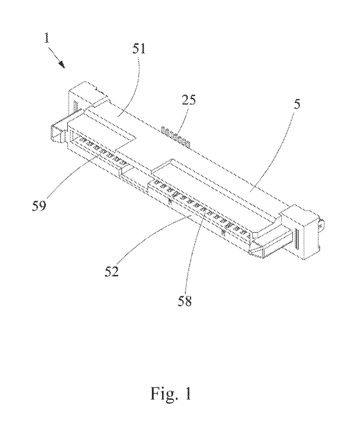
[0030]As shown in FIG. 1, an embodiment of the present disclosure discloses a high-frequency transmission electrical connector 1. The electrical connector 1 includes conductive terminals 2, insulation bodies 3, a conductive glue 4, and an insulation casing 5. The electrical connector 1 may be fixed on a circuit board (not shown), and may be docked with a docking device (not shown).

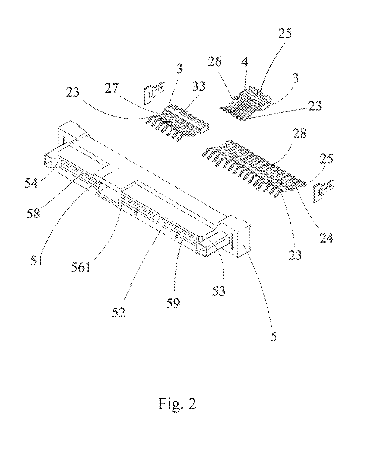
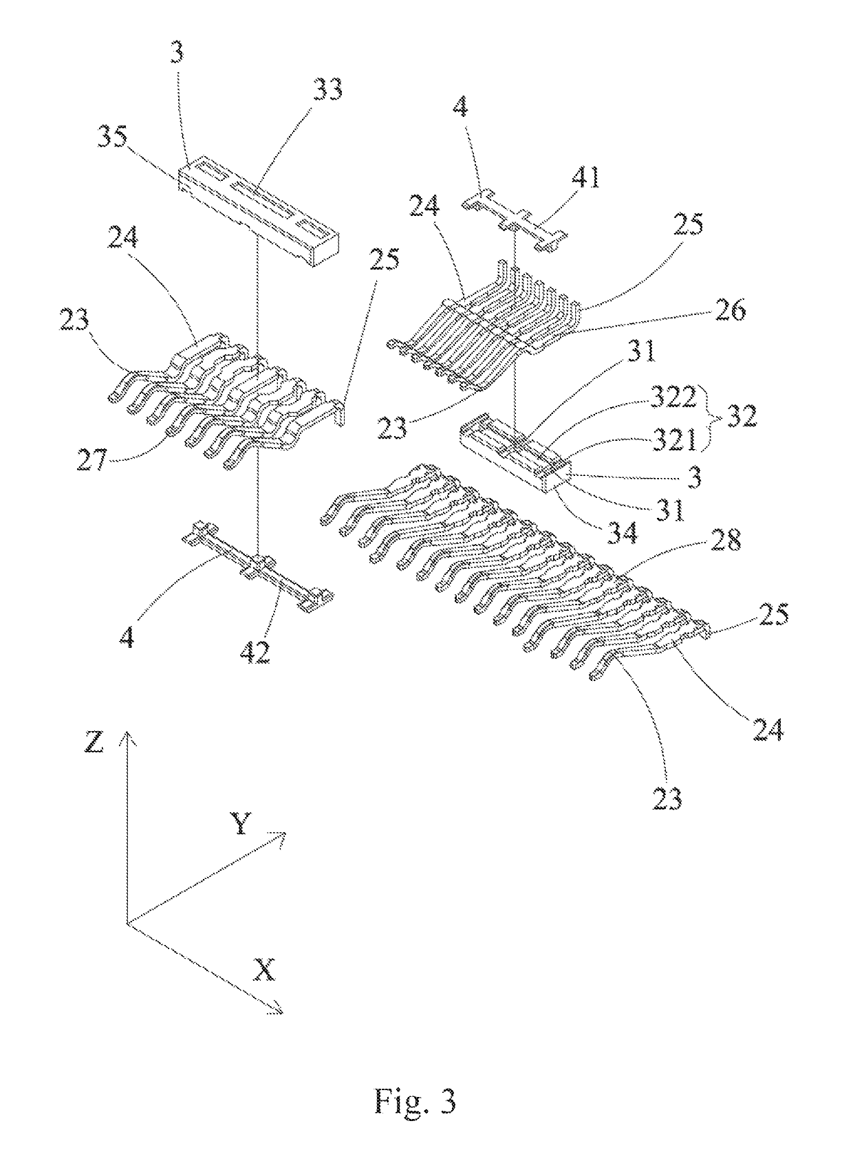
[0031]In an embodiment of the present disclosure, as shown in FIG. 2 and FIG. 3, the conductive terminals 2 of the electrical connector 1 include signal terminals 21 and grounding terminals 22. Each of the conductive terminals 2 includes a contact portion 23, a soldering portion 25, and a main portion 24 connecting the contact portio...


PUM


Abstract

An electrical connector includes a first terminal group, an insulation body, a conductive glue, and an insulation casing. The first terminal group includes grounding terminals and signal terminals. Each of the terminals in the first terminal group has a main portion. The insulation body is fixed to the main portion of each terminal of the first terminal group. The insulation body has openings exposing corresponding grounding terminals. The conductive glue fills the openings of the insulation body, and the conductive glue electrically connects the grounding terminals. The insulation casing includes a first side wall which includes first terminal slots. The first terminal group is disposed in the first terminal slots of the first side wall, and the conductive glue is sandwiched between the first side wall and the insulation body.

Description

CROSS-REFERENCE TO RELATED APPLICATION[0001]This application claims priority to Taiwan Application Serial Number 106217029, filed Nov. 15, 2017, which is herein incorporated by reference.BACKGROUND[0002]Field of Invention[0003]The present invention relates to an electrical connector structure. More particularly, the present invention relates to an electrical connector that is capable of adjusting high-frequency signal transmission.[0004]Description of Related Art[0005]With the rapid development of technology, the amount of data transmission increases accordingly, and thus conventional transmission devices cannot meet the current high efficiency requirements. An early Small Computer System Interface (SCSI) has been modified to become a current Serial Attached SCSI (SAS) which has broken through the upper limit of the original transmission speed. The SAS technology continues to improve in research and development, and thus the transmission speed is increased to 24.0 Gbps, in which the...

Claims


Application Information

Patent Timeline
IPC IPC(8): H01R13/64H01R13/6461H01R13/405
CPCH01R13/405H01R13/6461H01R4/04H01R13/6471
Inventor CHEN, LI-SENWU, CHU-CHENG
Owner SPEED TECH
Why Eureka
Try Eureka