Self-moving robot and walking method thereof
a robot and self-moving technology, applied in the field of self-moving robots and the walking method thereof, can solve the problems of large reduction in the cleaning efficiency of the robot and high cost of energy, and achieve the effects of low cost, high sensitivity and simple structur
- Summary
- Abstract
- Description
- Claims
- Application Information
AI Technical Summary
Benefits of technology
Problems solved by technology
Method used
Image

Examples
first embodiment
The First Embodiment
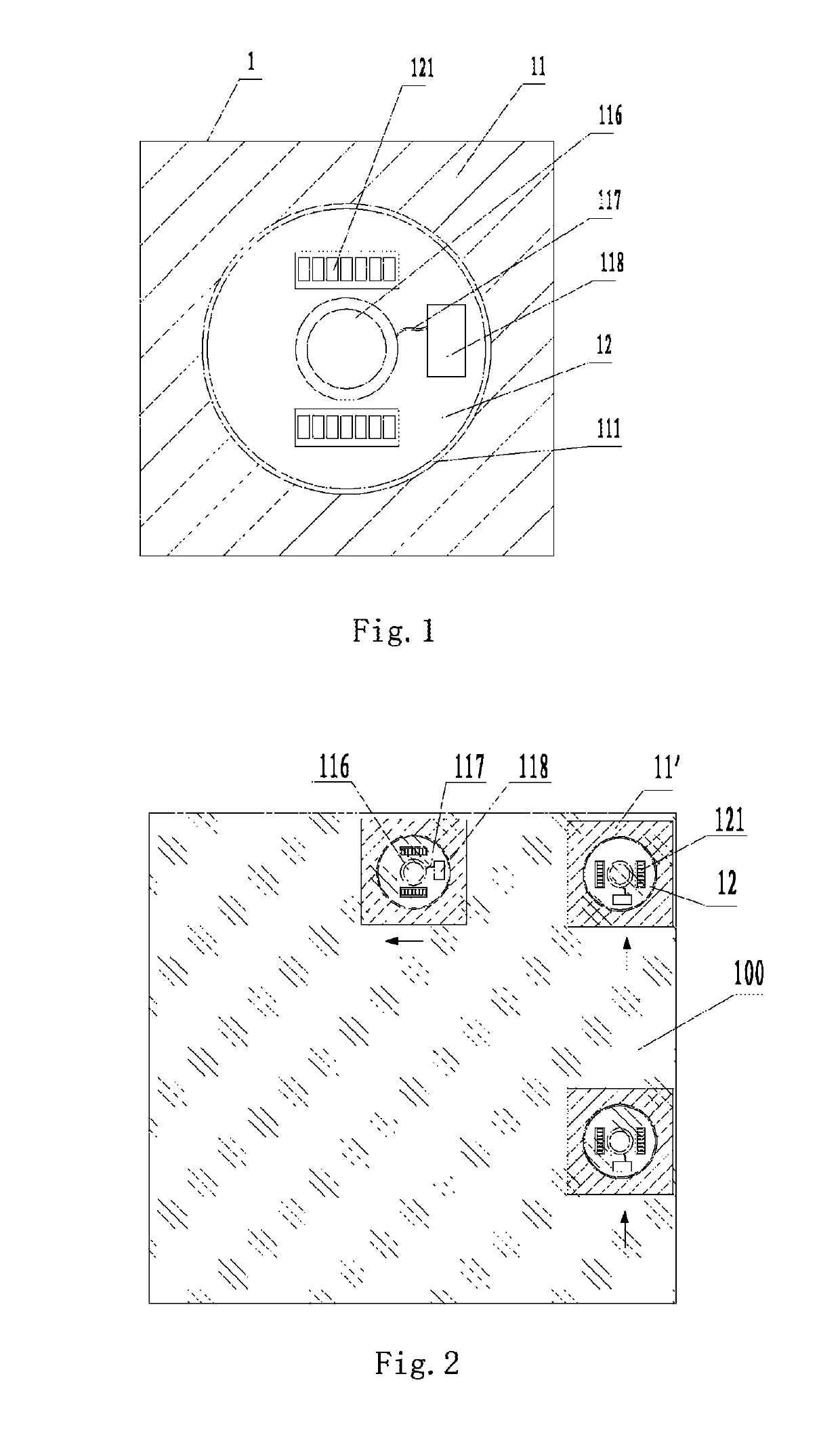
[0025]FIG. 1 is a schematic diagram of the overall structure of the first embodiment of the present invention. As shown in FIG. 1, the self-moving robot according to the present embodiment is a glass-wiping robot comprising a robot body 1. A control device is provided in the robot body 1, and a functional processing module 11 and a moving module 12 connected to each other are provided in the robot body 1. The moving module 12 is controlled by the control device to drive the functional processing module 11 to conduct mobile processing work in a working space. An opening hole 111 is formed inside the functional processing module 11, and the moving module 12 is arranged rotatably in the opening hole 111 in an embedded manner and rotatably attached to the functional processing module 11 through a connection mechanism. The functional processing module 11 is a glass surface cleaning module.
[0026]Furthermore, in the present embodiment, a first coupling end provided at t...
second embodiment
The Second Embodiment
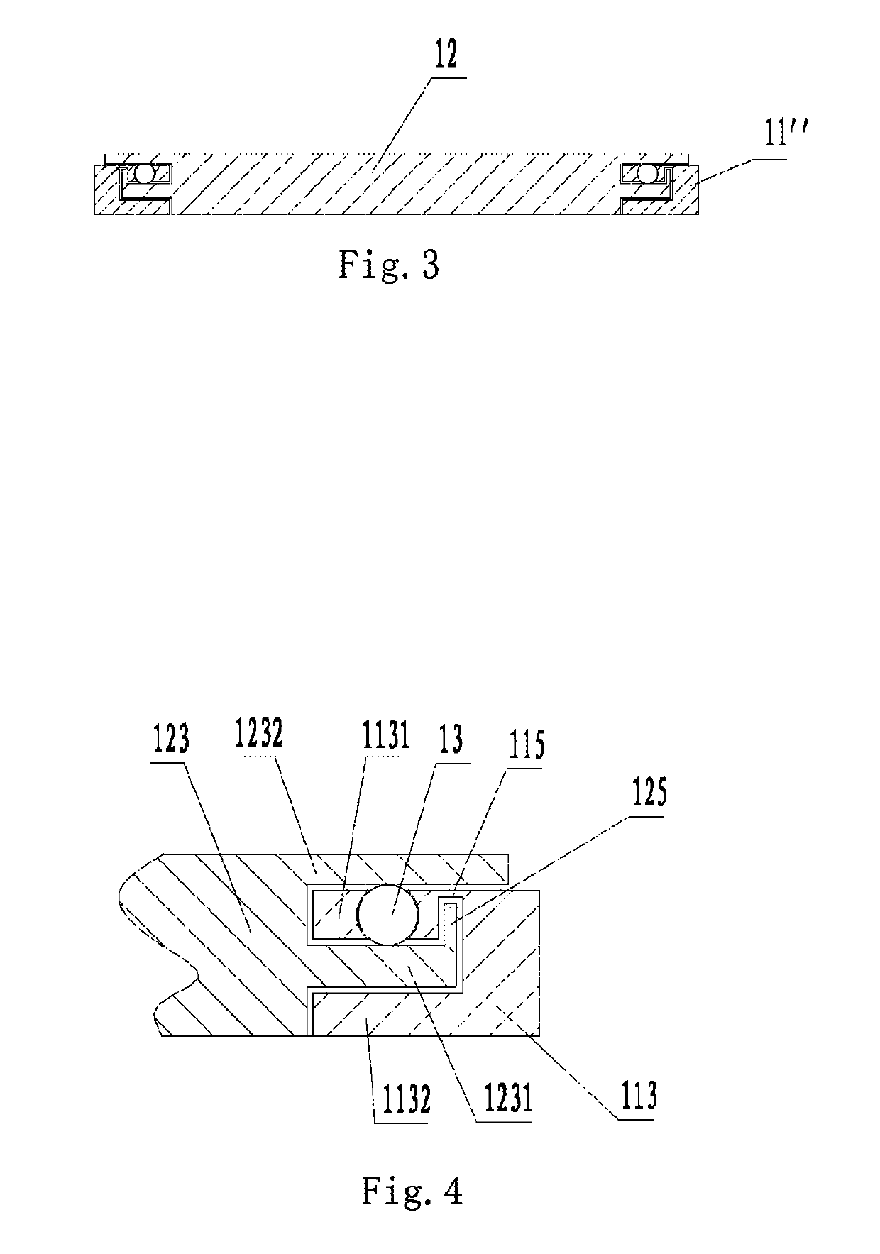
[0031]FIGS. 3 and 4 are a sectional view and a partial enlarged view of a ball mechanism of the second embodiment of the present invention respectively. As shown in FIGS. 3 and 4, the present embodiment provides a floor-sweeping robot, and its functional processing module is a floor-sweeping module 11″. As shown in FIG. 3, in the present embodiment, in order to facilitate a relative movement between the functional processing module and the moving module 12 as well as reduce wear between the functional processing module and the moving module 12, the connection mechanism is an coupling unit comprising a first coupling end 123 provided at the edge of the moving module 12 and a second coupling end 113 provided at the edge of the floor-sweeping module 11″. The first coupling end 123 and the second coupling end 113 are inserted into and positioned with each other, and a gap is remained between the coupling positions thereof. Each of the first coupling end 123 and the ...
third embodiment
The Third Embodiment
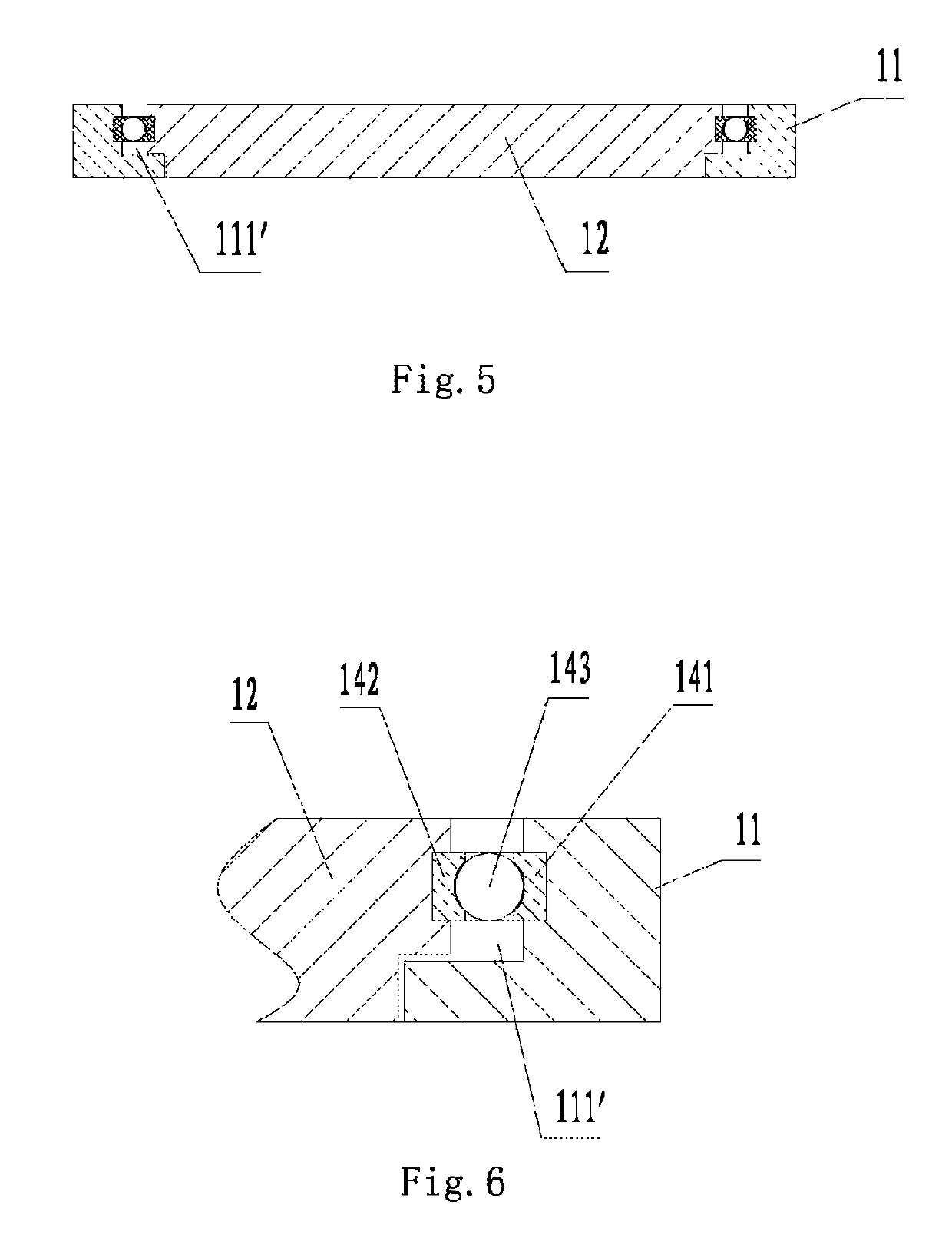
[0033]FIGS. 5 and 6 are a sectional view and a partial enlarged view of a roller bearing mechanism of the third embodiment of the present invention respectively. As shown in FIGS. 5 and 6, in order to facilitate the relative movement between the functional processing module 11 and the moving module 12 as well as reduce wear between the functional processing module 11 and the moving module 12, the connection mechanism may also be a roller bearing mechanism provided between the outer edge of the moving module 12 and the inner edge of an opening hole 111′ in the functional processing module. As shown in FIG. 6, the roller bearing mechanism includes an inner ring 142 provided at the outer edge of the moving module 12, an outer ring 141 provided at the inner edge of the opening hole 111′ in the functional processing module and balls 143 between the inner and outer rings. By replacing the sliding friction between the functional processing module 11 and the moving modul...
PUM
 Abstract
Description
Claims
Application Information
 - R&D
- Intellectual Property
- Life Sciences
- Materials
- Tech Scout
- Unparalleled Data Quality
- Higher Quality Content
- 60% Fewer Hallucinations
Browse by: Latest US Patents, China's latest patents, Technical Efficacy Thesaurus, Application Domain, Technology Topic, Popular Technical Reports.
© 2025 PatSnap. All rights reserved.Legal|Privacy policy|Modern Slavery Act Transparency Statement|Sitemap|About US| Contact US: help@patsnap.com