
Rotating and self aligning magnetic retention system

Active Publication Date: 2019-05-21
KUHN TODD +1
View PDF51 Cites 16 Cited by
  • Summary
  • Abstract
  • Description
  • Claims
  • Application Information

AI Technical Summary

Benefits of technology

The present invention provides a retentions system for beverage vessels that has a mounting surface without any indentations, holes, or cavities. This increases the space available when the vessel is not in use. The system also provides a magnetic force that increases during rotation to prevent spillage and make the vessel easier to hold. The use of autonomous magnetic holders eliminates the need for guide tracks and makes the attachment and detachment process faster and smoother. The system also reduces the jolt and impact of attachment and detachment.

Problems solved by technology

As a result, these smaller beverage containers can often spill and fall out when a vehicle is traveling over bumps, making turns and / or making sudden stops.
These large voids often require an enormous amount of wasted space both above and below the beverage holding structure.
However, the mere use of traditional magnets is flawed for all but the simplest of uses (i.e. refrigerator magnets, laptop chargers, purse closures and the like.).
If the magnets are strong they accelerate the object attaching to the other object creating a jolt and are difficult to detach.
If the magnets are weak their retention ability is limited.
Proximity between a magnet and a magnetic surface causes problems.
While touching magnets are very strong—with any distance between them they become exponentially weaker.
This feature can result in spilled beverages as the vessel and structure come into violent contact with each other.
This is an undesirable feature when hot beverages are housed in the beverage vessel, which can lead to personal injury to the user.
Additionally, the Fullerton et al. design is hampered when the user places the vessel in near-field alignment with the like polarities, causing a rapid rotation of the vessel (as the attracted polarities come into approximation of each other), twisting from the user's hand and most likely resulting in dangerous spillage.
Additionally, Alexander et al. does not teach of the use of retrofit kits as a means of securing any loose, vessel-like objects to any geometrically configured surface.

Method used


Image

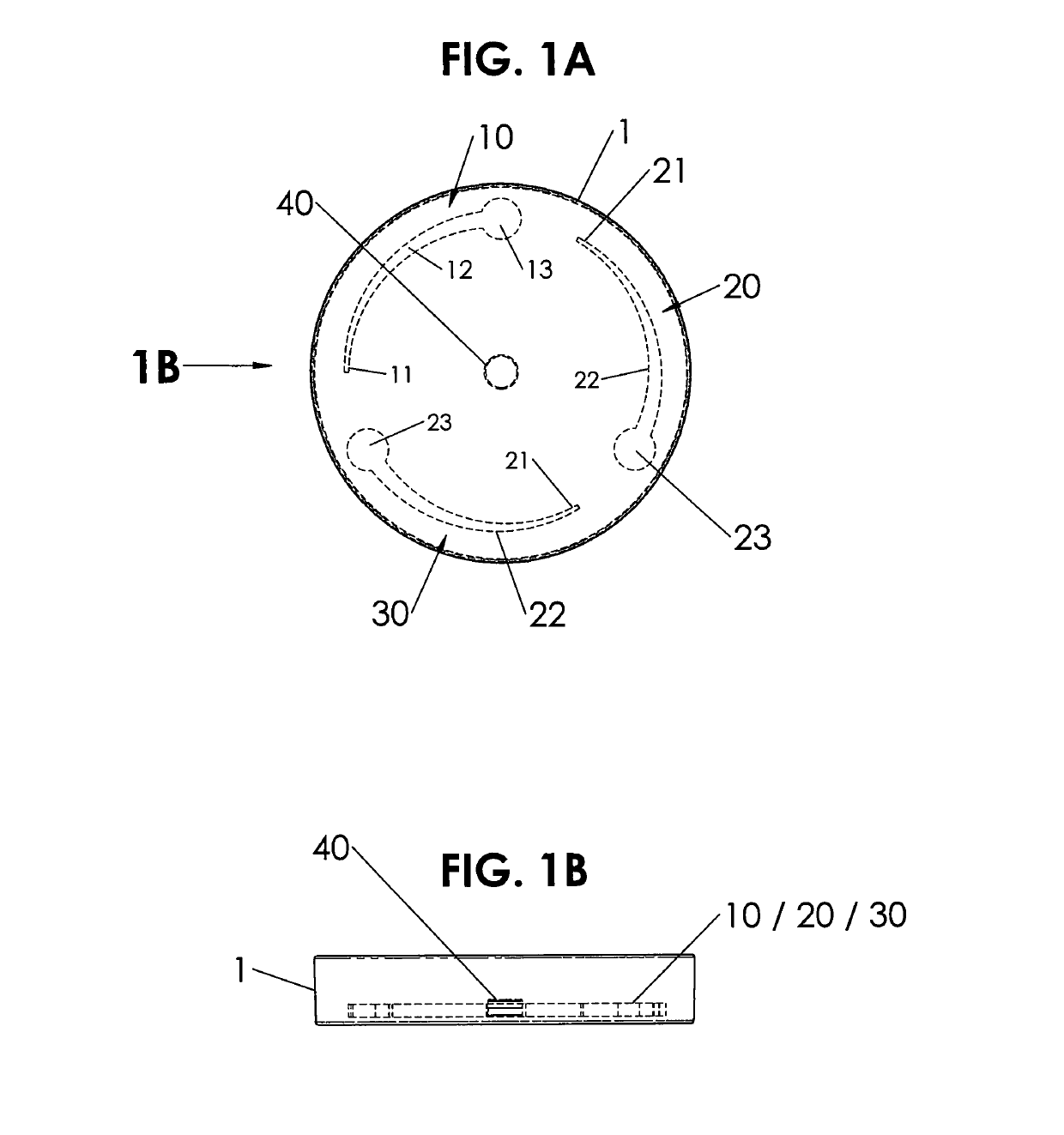
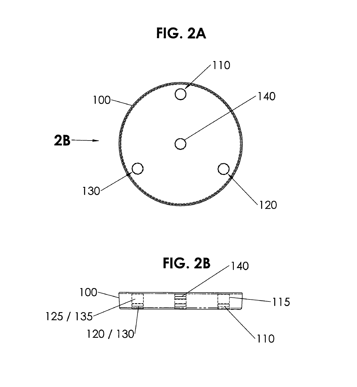
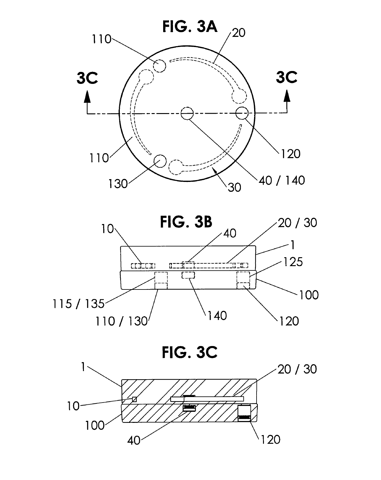
  • Rotating and self aligning magnetic retention system
  • Rotating and self aligning magnetic retention system
  • Rotating and self aligning magnetic retention system

Examples


embodiment 300

[0156]FIG. 8A is a side cross-sectional view of another embodiment 300 of a hub 310 with a single moveable magnet 330 with the magnet 330 in an up position in a channel 320. FIG. 8B is another view of the embodiment 300 of FIG. 8A with the moveable magnet 330 moved to the bottom 328 of the channel 320 when the hub 310 is placed on a surface 380 having metal.

[0157]The moveable magnet 330 can initially be located in the top 322 of the channel 320 by either the moveable magnet 330 being attracted to a fixed metal plate 340 in the top of the channel, or alternatively, by the moveable magnet 330 being repelled by the fixed magnet 350 in the bottom of the hub 310. As such, in this embodiment, either the fixed metal plate 340 or the fixed bottom magnet 350 are separately used.

[0158]Referring to FIGS. 8A-8B, hub 310 can be a beverage container such as an insulation sleeve that can fit about bottles or cans, or be part of the bottom of an existing beverage container as previously described. ...

embodiment 400

[0162]FIG. 9A is a side cross-sectional view of still another embodiment 400 of a hub 410 with a plurality of moveable magnets 430, 470 with the magnets 430, 470 in an up position in their respective channels 420, 460. FIG. 9B is another view of the embodiment 400 of FIG. 9A with the moveable magnets 430, 470 moved to the bottom 428, 468 of their channels 420, 460, when the hub 410 is placed on a surface 490 having metal.

[0163]The channels 420, 460 can be placed about the perimeter of the base of the hub 410 and spaced apart from one another. While two channels 420, 460 are shown, three or more channels, each with moveable magnets can be used.

[0164]Referring to FIGS. 9A-9BB, hub 410 can be a beverage container such as an insulation sleeve that can fit about bottles or cans, or be part of the bottom of an existing beverage container as previously described. A plurality of channels 420, 460 can be located in the base of the hub 410 having respective moveable magnets 430, 470. Initiall...


PUM


Abstract

The present invention relates to guideless, magnetic holders for beverage vessels and the like, and in particular, to devices, systems, sets and methods for providing paired, magnets for application onto, or manufacture thereinto, structures such as automobiles, boats, all-terrain vehicles (ATV's), snowmobiles, recreational vehicles (RV's), personal watercraft, golf carts, kayaks, appliances, tools, lawn tractors, farm equipment, motorcycles, furniture, coolers, stadium seating, and the like, or surface mounted, retrofit kits. A vessel component can be a metal plate with material having increasing width or increasing thickness. A hub support component can have at least one moveable magnet in a chamber, the moveable magnet being initially repulsed by a fixed magnet to a bottom of the chamber. Positioning and rotating the component over the hub increases the magnetic attraction so that the at least one moveable magnet moves upward to a top of the chamber causing a click noise signifying a strong magnetic lock position between the vessel component and the hub. The holder can be used with at least one channel having a moveable magnet therein, where the holder can be attachable to a metal surface.

Description

CROSS REFERENCE TO RELATED APPLICATIONS[0001]This application claims the benefit of priority to U.S. Provisional Application Ser. No. 62 / 395,542 filed Sep. 16, 2016, the entire disclosure of which is incorporated by reference in its' entirety.FIELD OF INVENTION[0002]The present invention relates to guideless, trackless, magnetic holders for beverage vessels and the like, and in particular, to devices, systems, sets and methods for providing magnets for application onto, or manufacture thereinto, structures such as automobiles, boats, (all-terrain vehicles (ATV's), snowmobiles, recreational vehicles (RV's), personal watercraft, lawn tractors, farm equipment, motorcycles, golf carts, kayaks, furniture, coolers, ice chests, stadium seating, and the like, or surface mounted, retrofit kits, which includes a cup / vessel support component for a beverage, the component having a metal plate with material having increasing width and / or increasing thickness, along with a hub support component h...

Claims


Application Information

Patent Timeline
IPC IPC(8): H01F7/20A47G23/02B63B17/00B65D25/20A47C7/68F16B1/00F16M13/02B60N3/10B60R11/00
CPCA47G23/0225F16B1/00F16M13/02B60N3/101A47C7/68B65D25/20B63B17/00B60R2011/0057F16B2001/0035A47G2200/106F16M11/041F16M13/022B63B29/04B60N3/103F16B2200/83
Inventor KUHN, TODDCAMPBELL, JASON P.
Owner KUHN TODD
Learn More