Method and system for improved dilution purging

a technology of dilution purging and purging chamber, which is applied in the direction of engine starters, vehicle sub-unit features, electric control, etc., can solve the problems of increasing the propensity for engine misfire, increasing the stability of combustion, and increasing the number of engine misfires, so as to reduce throttling losses and combustion temperatures, improve fuel economy and vehicle emissions, and improve the effect of fuel economy

Active Publication Date: 2019-05-21
FORD GLOBAL TECH LLC
View PDF20 Cites 5 Cited by
  • Summary
  • Abstract
  • Description
  • Claims
  • Application Information

AI Technical Summary

Benefits of technology

[0002]Exhaust gas recirculation (EGR) systems recirculate a portion of exhaust gas from an engine exhaust to an engine intake system to improve fuel economy and vehicle emissions by reducing throttling losses and combustion temperatures. In turbo-charged direct injection engines, a low-pressure EGR (LP-EGR) circuit may be implemented. The LP-EGR circuit recirculates exhaust gases from an exhaust passage downstream of a turbine to an intake passage upstream of a turbocharger compressor.
[0003]However, due to the pre-compressor location of EGR delivery, there may a significant transport delay between the EGR valve and the combustion chamber. Specifically, the exhaust residuals may need to travel though the turbocharger compressor, high-pressure air induction plumbing, charge air cooler, and intake manifold before reaching the combustion chamber. As a result of the transport delay, during conditions when EGR needs to be rapidly reduced, such as during a tip-out to low load conditions, there may be more dilution in the intake than desired. The presence of increased intake-air dilution at low loads can increase combustion stability issues and the propensity for engine misfires.
[0006]The inventors have recognized that at least some of the above issues may be addressed by using a motor / generator of a hybrid vehicle system to rapidly purge LP-EGR. In one example, this is achieved by a method for a hybrid vehicle system comprising: in response to decreasing engine load while operating an engine with EGR, disabling fuel to the engine while using motor torque to propel the vehicle; and spinning the engine unfueled via a generator until EGR in the intake is less than a threshold. In this way, LP-EGR can be rapidly purged without affecting torque to the wheels.
[0008]In this way, EGR purging from an engine intake can be expedited. By actively spinning the engine unfueled via a motor / generator, with an intake throttle and an EGR valve open, pumping work of the spinning engine can be used to draw in fresh air and expel EGR from the intake manifold. As such, this enables EGR levels in the intake manifold to be reduced faster than would have been otherwise possible. In addition, higher engine torque and battery charge may be held while EGR is purged. By rapidly reducing the intake EGR level at low load conditions when the engine is shutdown, higher EGR rates can be achieved when the engine is subsequently restarted. As such, this substantially improves engine efficiency, particularly in medium to high engine speed-load regions. By replacing the EGR with fresh air, evaporation of water and hydrocarbon condensates is increased, reducing their concentration in the engine, and the need for counter-condensation measures. In addition, the reduction in condensation reduces compressor and charge air cooler corrosion and degradation. Overall, boosted engine performance is improved.

Problems solved by technology

However, due to the pre-compressor location of EGR delivery, there may a significant transport delay between the EGR valve and the combustion chamber.
The presence of increased intake-air dilution at low loads can increase combustion stability issues and the propensity for engine misfires.
However, the inventors herein have recognized potential issues with such an approach.
As an example, the transport delay may not be sufficiently addressed while the fuel economy benefits of LP-EGR are limited.
For example, the linking of EGR dilution to intake airflow may result in LP-EGR being provided at some low load points where no fuel economy benefit from the EGR is achieved.
In some cases, there may even be a fuel penalty associated with the delivery of LP-EGR at the low load point.
As such, it may not be possible to rapidly purge the LP-EGR from the intake in such systems without affecting airflow.
As another example, the lower load points may limit the delivery of EGR at higher load points as they are the points where the combustion system is most dilution limited.
As such, this can limit the peak EGR rates achievable during high loads.
The presence of excess dilution in the engine intake system can also render the compressor susceptible to corrosion and condensation from the lingering EGR.
Furthermore, increased condensation may occur at a charge air cooler of a boosted engine system due to the flow of EGR through the cooler.
In response to a tip-out to lower load conditions, fuel injection to the engine may be disabled and motor torque from an electric motor / generator may be used to propel the vehicles.

Method used


Image

  • Method and system for improved dilution purging
  • Method and system for improved dilution purging
  • Method and system for improved dilution purging

Examples


Embodiment Construction

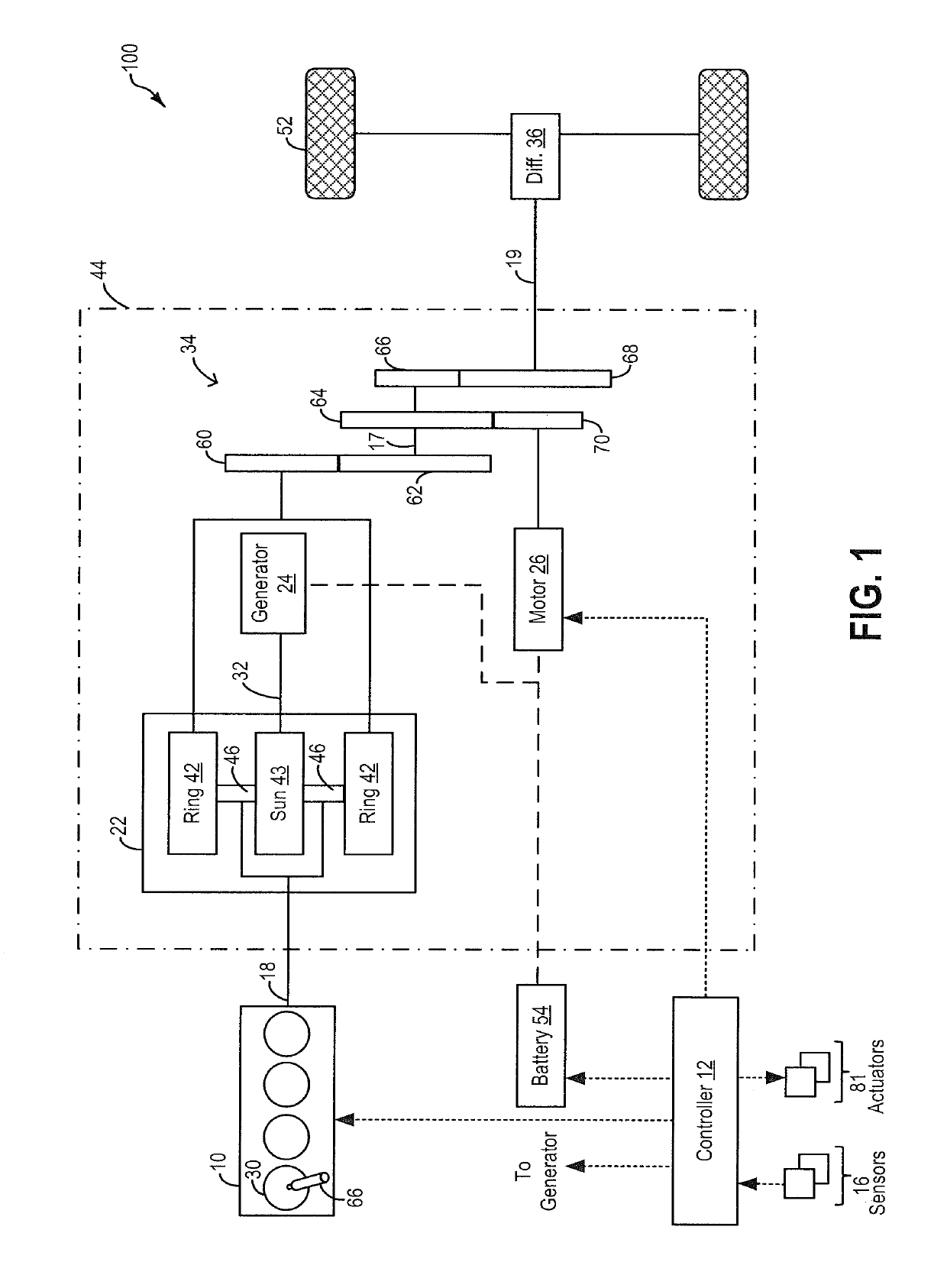
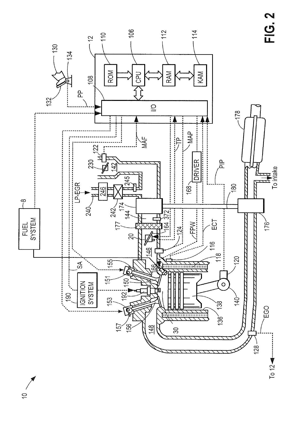
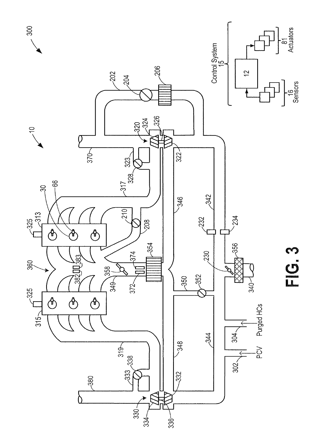
[0016]The following description relates to systems and methods for using a motor / generator of a hybrid vehicle system (such as the vehicle system of FIG. 1) to expedite purging of EGR from an engine (such as the engine system of FIGS. 2-3) at low load conditions. While operating the hybrid vehicle in an engine mode, with EGR flowing, in response to decreasing engine load, EGR delivery to the engine may need to be rapidly reduced. During such conditions, a controller may be configured to perform a control routine, such as the example routine of FIG. 4, to disable fuel to the engine and propel the vehicle using motor torque. In addition, the controller may spin the engine, unfueled, using motor torque, for a duration until EGR is sufficiently purged from the engine's intake manifold. Alternatively, if the vehicle system battery is capable of accepting charge, the controller may disable EGR and operate the engine with the EGR valve closed while storing the excess engine torque generate...


PUM


Abstract

Methods and systems are provided for expediting EGR purging in a hybrid vehicle during transient operations, such as tip-out to lower load conditions. In response to decreasing engine torque demand, engine fueling is disabled and a motor is used to spin the engine unfueled until a desired LP-EGR rate is achieved. Alternatively, engine operation is maintained with EGR disabled until the desired LP-EGR rate is achieved, and the excess engine torque generated is stored in a system battery.

Description

TECHNICAL FIELD[0001]The present application relates to methods and systems for improving purging of low pressure EGR from an engine during operation at light loads.BACKGROUND AND SUMMARY[0002]Exhaust gas recirculation (EGR) systems recirculate a portion of exhaust gas from an engine exhaust to an engine intake system to improve fuel economy and vehicle emissions by reducing throttling losses and combustion temperatures. In turbo-charged direct injection engines, a low-pressure EGR (LP-EGR) circuit may be implemented. The LP-EGR circuit recirculates exhaust gases from an exhaust passage downstream of a turbine to an intake passage upstream of a turbocharger compressor.[0003]However, due to the pre-compressor location of EGR delivery, there may a significant transport delay between the EGR valve and the combustion chamber. Specifically, the exhaust residuals may need to travel though the turbocharger compressor, high-pressure air induction plumbing, charge air cooler, and intake mani...

Claims


Application Information

Patent Timeline
Patent Type & Authority Patents(United States)
IPC IPC(8): F02D41/12F02D41/04B60W20/00F02D17/04F02D41/00F02N11/08F02M25/08F02D13/02F02M26/02
CPCF02D17/04B60W20/00F02D41/0055F02D41/0065F02D41/042Y02T10/47F02D2041/0017F02D2250/24F02M25/08F02M26/02F02N11/0844F02D13/02B60W10/06B60W10/08B60W20/16B60W2510/068B60W2510/244B60W2540/10B60W2710/0644B60W2710/083B60Y2400/442Y02T10/40Y02T10/62
Inventor STYLES, DANIEL JOSEPHBOWER, STANLEY LARUEHILDITCH, JAMES ALFREDIORIO, ROBERT RALPHSURNILLA, GOPICHANDRA
Owner FORD GLOBAL TECH LLC
Why Eureka
Try Eureka