Crankshaft and method of strengthening shaft component

a technology of crankshaft and shaft component, which is applied in the direction of heat treatment furnaces, heat treatment equipment, furnaces, etc., can solve the problems of crankshaft extension in a shaft direction, uneconomical processing time and effort, and bending, etc., and achieves tension residual stress, short time-consuming, and strong

Active Publication Date: 2019-05-28
HONDA MOTOR CO LTD
View PDF6 Cites 0 Cited by
  • Summary
  • Abstract
  • Description
  • Claims
  • Application Information

AI Technical Summary

Benefits of technology

[0007]Therefore, an object of the present invention is to provide a crankshaft and a strengthening method of a shaft member, which can be strengthened in a short time without being subjected to wasteful processing, and which can be strengthened over a wide range. Furthermore, an object of the present invention is to provide a crankshaft and a strengthening method for a shaft member, in which the tension residual stress generated at a portion that adjoins the portion in which the compressive residual stress is applied, can be decreased by gradually applying the compressive residual stress from the portion required to be strengthened to a portion not required to be strengthened.Means for Solving the Problems
[0021]According to the strengthening method of the present invention, the crankshaft or the shaft member can be strengthened in a short time without being subjected to wasteful processing, and can be strengthened over a wide range. Furthermore, according to the present invention, the tension residual stress generated at a portion that adjoins a portion to be strengthened, can be decreased by gradually applying the compressive residual stress from a portion required to be strengthened to a portion not required to be strengthened.

Problems solved by technology

However, the above strengthening method strengthens the entire circumference of the fillet portion, containing portions that do not require strengthening, and therefore, the time and effort for processing are uneconomical.
Furthermore, the method simultaneously subjects the entire circumference of all fillet portions on the crank pins and the journal pins to plasticity processing, and as a result, the crankshaft is extended in a shaft direction and is bent.

Method used


Image

  • Crankshaft and method of strengthening shaft component
  • Crankshaft and method of strengthening shaft component
  • Crankshaft and method of strengthening shaft component

Examples


first embodiment

1. First Embodiment

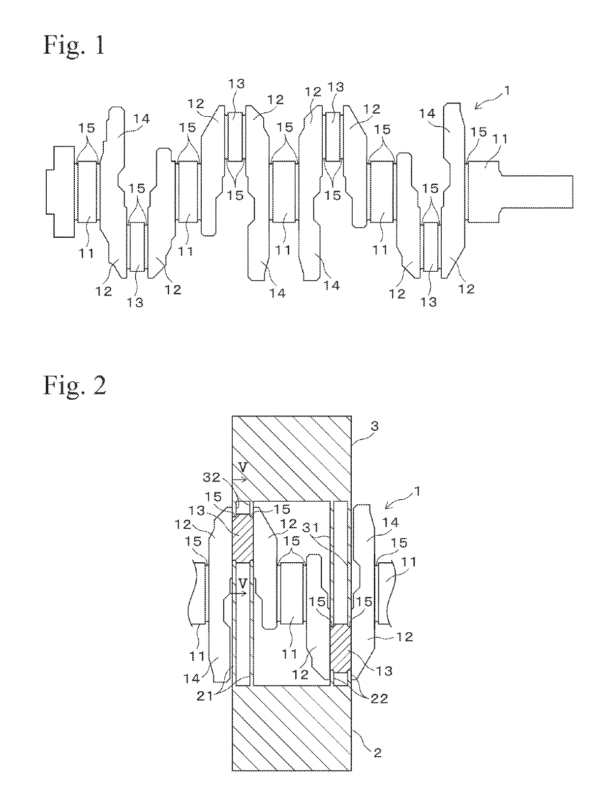
[0030]In the following, a first embodiment of the present invention will be explained with reference to figures. FIG. 1 is a side view showing a crankshaft 1 according to the first embodiment of the present invention. The crankshaft 1 is formed by hot forging, and it has a structure in which crank arms 12 which protrude in a radial direction are formed on a journal pin 11 which is a rotating shaft, a crank pin 13 is bridged between edges of a pair of the crank arms 12, and a balance weight 14 is formed on another edge of a pair of the crank arms 12. At both corners of each journal pin 11 and each crank pin 13, fillet portions 15, which are grooves in a cross-sectional semicircle shape, are formed.

[0031]FIG. 2 shows a state in which the fillet portions 15 of the crank pins 13 are subjected to plasticity processing by a lower die 2 and an upper die 3. The crankshaft 1 is carried on the die 2 so that the crank pins 13 are oriented in a perpendicular direction. At one...

second embodiment

2. Second Embodiment

[0048]A second embodiment of the present invention will be explained with reference to FIGS. 7 and 8. FIG. 7 is a perspective side view showing a first lower punch 121 and a second upper punch 132. A pressing surface 133 is formed on an underside of the second upper punch 132. The pressing surface 133 has a formed section A in a range within 45 degrees at both sides in a circumferential direction from a normal line I direction (a direction from the center of curvature O to a center line of the second upper punch 132), which is an approximately cylindrical curved surface having radius of curvature which subtracts a pressing amount from radius of curvature of a cross-section of a fillet portion 15. Here, “the pressing amount” means a thickness in which the fillet portion 15 is processed along the normal line I by the pressing surface 133. The formed section A is almost equally processed by the pressing surface 133.

[0049]As shown in FIG. 8, the pressing surface 133 ...


PUM

PropertyMeasurementUnit
angleaaaaaaaaaa
compressive residual stressaaaaaaaaaa
radius of curvatureaaaaaaaaaa

Abstract

A crankshaft that can be strengthened in a short time without being subjected to wasteful processing, and that can be strengthened over a wide range. The crankshaft includes a crank pin and a fillet portion of a journal pin. Compressive residual stress is applied to a region on the fillet portion, which extends at almost equal distances to both sides in a circumferential direction from a portion in which the greatest bending load is applied, and a processing depth for applying the compressive residual stress is gradually decreased in a circumferential direction from the center position in which the compressive residual stress is greatest.

Description

TECHNICAL FIELD[0001]The present invention relates to a crankshaft and to a method for strengthening a member having a shaft, and in particular, relates to a technique for strengthening to withstand bending load or torsional stress applied to a crank pin or a journal pin.BACKGROUND ART[0002]For example, a crankshaft has a journal pin and a crank pin, and a larger end portion of a connecting rod is rotatably supported at the crank pin, and the journal pin is rotatably supported at a journal bearing of an engine block. In order to avoid interference with a mated member, grooves in a cross-sectional semicircular shape (fillet portion) are formed at corner portions of the crank pin and the journal pin. The fillet portion is a portion having low strength, and a large bending moment is applied to the portion when there is an explosion in the internal combustion engine. Therefore, it is desired that a pin top portion (positions at 0 degrees phase and 180 degrees phase in the case of an inl...

Claims


Application Information

Patent Timeline
Patent Type & Authority Patents(United States)
IPC IPC(8): B21D3/16C21D7/04C21D9/30F02B75/32B21K1/08F16C3/08
CPCB21K1/08C21D7/04F02B75/32F16C3/08C21D9/30F16C2202/06
Inventor TANAKA, TOSHIYUKIMIURA, DAISUKEYOSHIMURA, TAKUROTAKEUCHI, YUTAKAKOSHINO, DAISUKE
Owner HONDA MOTOR CO LTD
Why Eureka
Try Eureka