Construction machine

a construction machine and construction technology, applied in mechanical machines/dredgers, soil shifting machines/dredgers, constructions, etc., can solve the problems of low efficiency and high processing load involved, and achieve the effect of efficient and accurate acquisition of target surfa

Active Publication Date: 2019-05-28
NIHON KENKI CO LTD
View PDF36 Cites 10 Cited by
  • Summary
  • Abstract
  • Description
  • Claims
  • Application Information

AI Technical Summary

Benefits of technology

[0008]The existing target surface acquisition method requires that step S001 to step S004 above be carried out as many times as the number of design surfaces in a single control cycle. The processing load involved is high and efficiency is low, which are problems with the existing method.
[0012]The present invention has been made in view of the above circumstances and provides as an object a construction machine that acquires efficiently and accurately the target surface to be displayed or controlled.
[0014]The present invention envisages acquiring as the target surface one of multiple design surfaces that is highly likely to come into contact with the work equipment. This permits efficient and accurate acquisition of the target surface to be displayed or controlled.

Problems solved by technology

This technology has incurred the following problems.
The processing load involved is high and efficiency is low, which are problems with the existing method.

Method used


Image

  • Construction machine
  • Construction machine
  • Construction machine

Examples


first embodiment

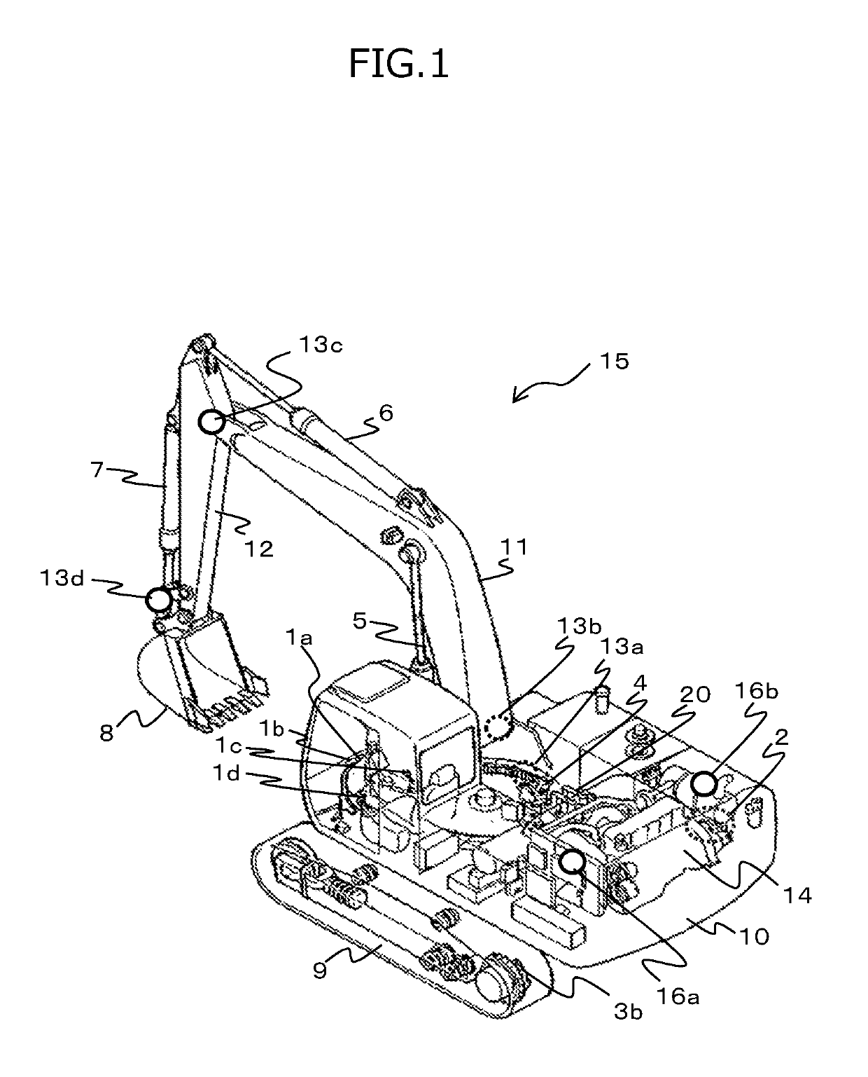
[0037]FIG. 1 is a perspective view showing a first embodiment of a construction machine according to the present invention. As shown in FIG. 1, the hydraulic excavator 1 includes a lower track structure 9, an upper swing structure 10, and work equipment 15. The lower track structure 9 has right and left crawler travel devices driven by right and left traveling hydraulic motors 3a and 3b, respectively (the left traveling hydraulic motor 3b alone is shown). The upper swing structure 10 is mounted swingably on the lower track structure 9 and driven swingably by a swing hydraulic motor 4. The upper swing structure 10 is equipped with an engine 14 acting as a prime mover and a hydraulic pump device 2 driven by the engine 14. The lower track structure 9 and the upper swing structure 10 constitute the vehicle body.

[0038]The work equipment 15 is attached tiltably to the front of the upper swing structure 10 constituting the vehicle body. The upper swing structure 10 has a cabin in which are...

second embodiment

[0098]A second embodiment of the construction machine according to the present invention is described below using the accompanying drawings. FIG. 12 is a block diagram showing a target surface acquisition unit of the controller constituting part of the second embodiment of the construction machine according to the present invention. FIG. 13A is a flowchart showing the processing sequence of an estimated target surface calculation unit as part of the second embodiment of the construction machine according to the present invention. FIG. 13B is a conceptual view explanatory of a typical process performed by the estimated target surface calculation unit as part of the second embodiment of the construction machine according to the present invention. Of the reference characters in FIGS. 12 to 13B, those also found in FIGS. 1 to 11 denote the same or corresponding parts that will not be discussed further in detail.

[0099]In the second embodiment of the construction machine according to the ...


PUM


Abstract

A construction machine acquires efficiently and accurately the target surface to be displayed or controlled. The construction machine includes: a design surface information storage unit storing three-dimensional target shape as multiple design surfaces; a work equipment velocity vector acquisition unit detecting or estimating the velocity of work equipment; a work equipment position acquisition unit detecting or estimating the position of the work equipment; a target surface acquisition unit acquiring a principal target surface to acquire an estimated target surface that is potentially the next principal target surface; an operation control unit correcting the work equipment velocity; and a display unit displaying the positional relations between the work equipment position and the principal target surface. The target surface acquisition unit includes an estimated target surface calculation unit determining as an estimated target surface the design surface located in the direction of the work equipment velocity vector.

Description

BACKGROUND OF THE INVENTION1. Field of the Invention[0001]The present invention relates to a construction machine.2. Description of the Related Art[0002]Excavation support devices are known to support the operator's operation of a construction machine in the excavating work using the machine to form the original shape into three-dimensional target shape. Such excavation support devices typically include, in place of the existing finishing stake for construction, machine guidance that replaces with a monitor for displaying positional relations between the target shape and the work equipment of the construction machine, and machine control that controls the construction machine in semi-automatic fashion in accordance with positional deviations between the target shape and the work equipment.[0003]These excavation support devices store the three-dimensional target shape in the form of information about multiple design surfaces. A target surface to be displayed or controlled is acquired...

Claims


Application Information

Patent Timeline
Patent Type & Authority Patents(United States)
IPC IPC(8): E02F3/43E02F9/20E02F9/26E02F3/32
CPCE02F3/439E02F3/32E02F9/265E02F9/2041E02F9/262E02F9/2004E02F3/43E02F3/435E02F9/264
Inventor MORIKI, HIDEKAZUYAMADA, HIROYUKIEDAMURA, MANABUSAKAMOTO, HIROSHI
Owner NIHON KENKI CO LTD
Why Eureka
Try Eureka