Fuel tank structure

a fuel tank and structure technology, applied in the direction of fuel injection apparatus, charge feed system, non-fuel substance addition to fuel, etc., can solve the problems of increasing the complexity of the structure, increasing the loss of pumping, and increasing the difficulty of improving the fuel consumption, so as to improve the efficiency of evaporative fuel recovery, and improve the effect of fuel consumption

Inactive Publication Date: 2019-05-28
TOYOTA JIDOSHA KK
View PDF50 Cites 6 Cited by
  • Summary
  • Abstract
  • Description
  • Claims
  • Application Information

AI Technical Summary

Benefits of technology

[0007]However, in the fuel tank structure disclosed in Japanese Patent Publication No. 5299565, in addition to the gas separator that is used to reduce the internal pressure in the fuel tank, a mechanism to switch opening / closing of the canister and the gas separator is also required, so that the complexity of the structure increases. Moreover, because energy (i.e., power) to operate the gas separator is also required, there is also room for improvement from the standpoint of improving fuel consumption.
[0008]In consideration of the above circumstances, an object of preferred embodiments is to provide a fuel tank structure that makes it possible to improve fuel consumption by means of simple structure.

Problems solved by technology

In this kind of structure, because the evaporative fuel that has been adsorbed in the canister is purged using negative pressure from the intake manifold, pumping loss increases and it is difficult to improve fuel consumption.
However, in the fuel tank structure disclosed in Japanese Patent Publication No. 5299565, in addition to the gas separator that is used to reduce the internal pressure in the fuel tank, a mechanism to switch opening / closing of the canister and the gas separator is also required, so that the complexity of the structure increases.

Method used


Image

  • Fuel tank structure
  • Fuel tank structure
  • Fuel tank structure

Examples


Embodiment Construction

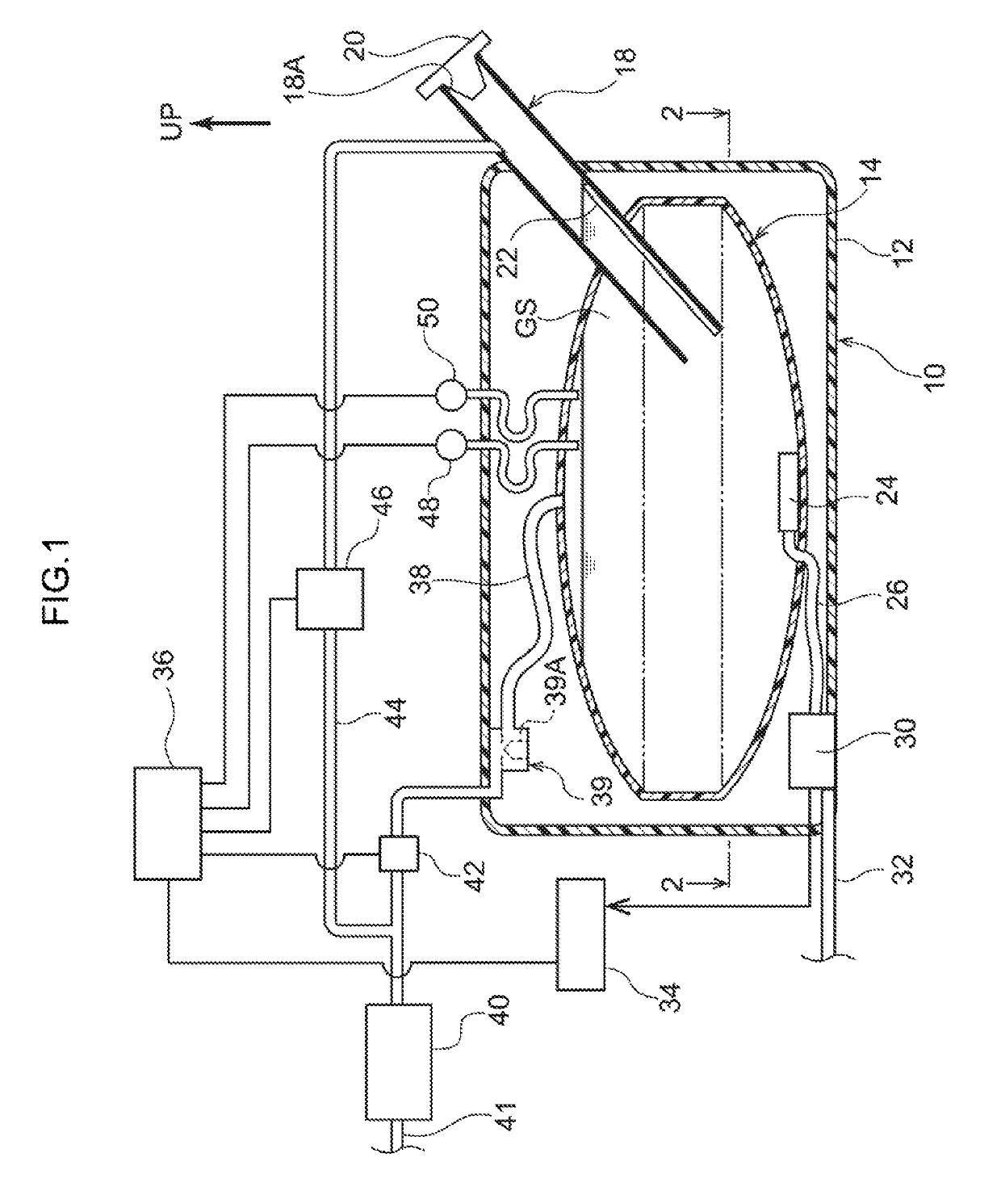
[0026]Hereinafter, a fuel tank structure according to an embodiment will be described. Note that an arrow UP that is shown in the respective drawings shows the upward side of the fuel tank. Moreover, in the embodiments, the upward side of the fuel tank coincides with the upward side in the vertical direction of the vehicle.

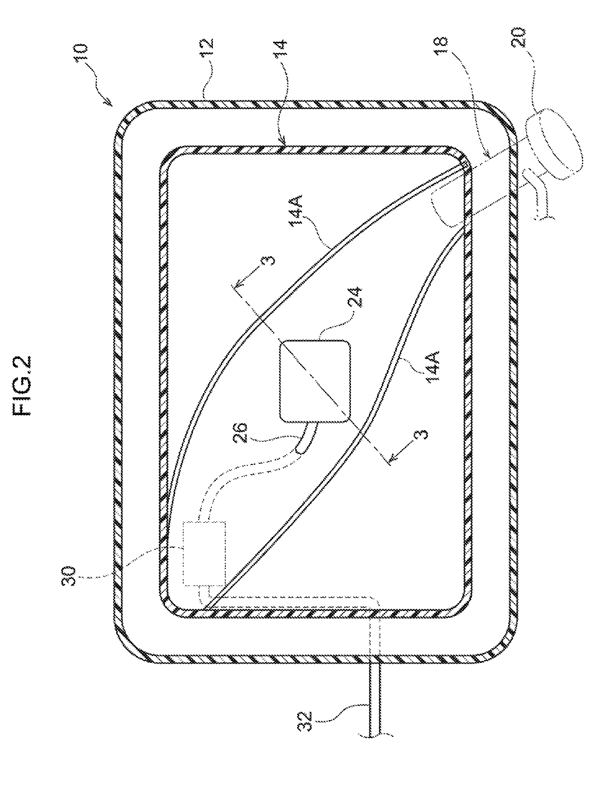
[0027]As is shown in FIG. 1, a fuel tank 10 that forms a fuel tank structure according to the present embodiment includes a tank main body portion 12 and a holding portion 14. The tank main body portion 12 is hollow, and makes up an outer shell of the fuel tank 10. A bottom surface of the tank main body portion 12 is supported by a tank band (not shown). The tank main body portion 12 is mounted on a floor panel (not shown) by fixing the tank band to the floor panel with a bracket or the like.

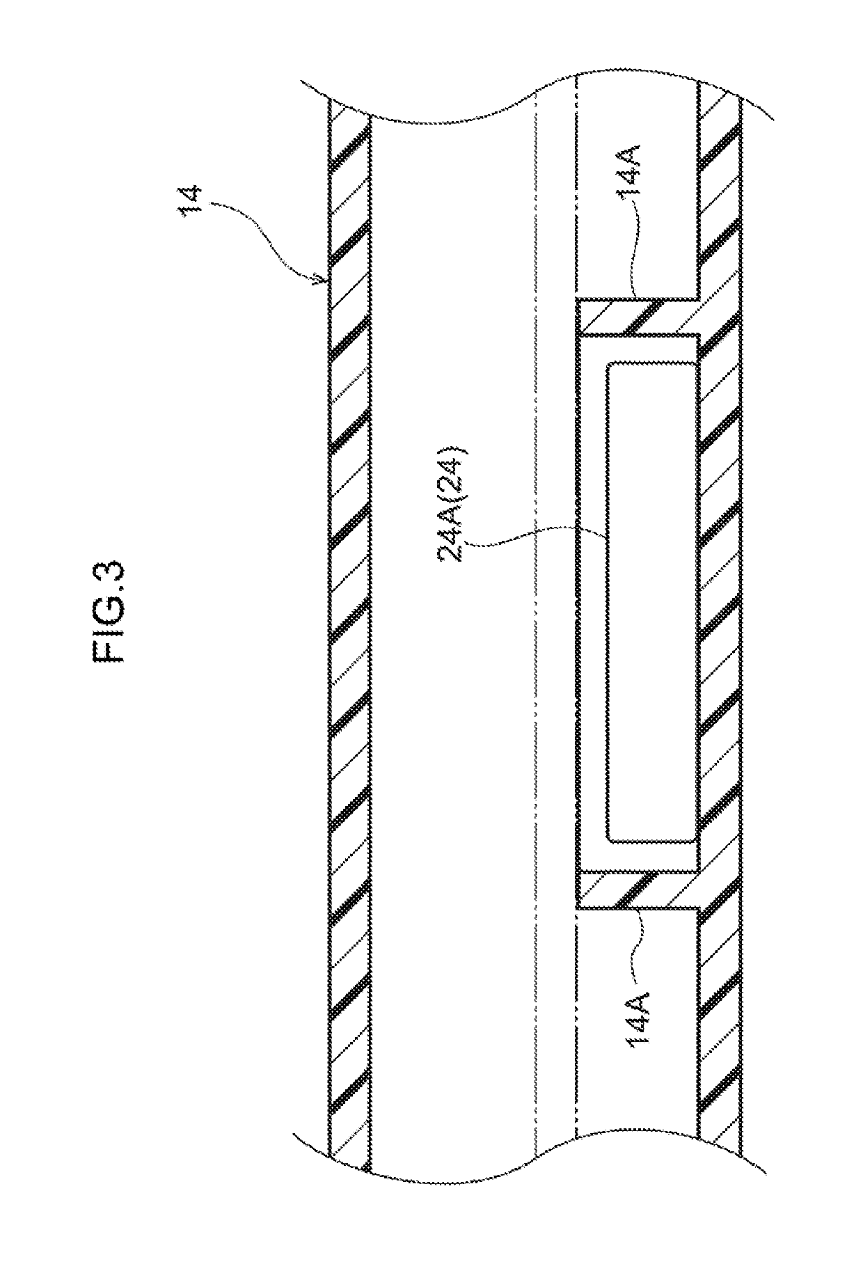
[0028]The holding portion 14 is provided inside the tank main body portion 12. The holding portion 14 is formed such that it is able to expand and contract, and is formed in a...


PUM


Abstract

A fuel tank structure comprising a fuel tank; a canister; a first pipe that joins together a holding portion of the fuel tank and the canister; a first shut-off valve provided at the first pipe; a filler pipe; a second pipe that joins together the filler pipe and the canister; a second shut-off valve provided at the second pipe; a pressure sensor that detects the pressure inside the holding portion; a fuel pump that feeds the fuel to an engine; and a control unit. The control unit opens the first shut-off valve during refueling such that evaporative fuel is permitted to move from the holding portion to the canister, and closes the first shut-off valve after refueling. The control unit opens the second shut-off valve when the pressure inside the holding portion detected by the pressure sensor drops below a predetermined pressure which is lower than the atmospheric pressure.

Description

CROSS-REFERENCE TO RELATED APPLICATION[0001]This application is based on and claims priority under 35 USC 119 from Japanese Patent Application No. 2015-148038 filed on Jul. 27, 2015, the disclosure of which is incorporated by reference herein in its entirety.BACKGROUND[0002]Technical Field[0003]Preferred embodiments relate to a fuel tank structure.[0004]Related Art[0005]A structure in which a canister is provided in order to adsorb evaporative fuel (i.e., fuel vapor) is known as a structure for a fuel tank that is mounted in an automobile. In this kind of structure, because the evaporative fuel that has been adsorbed in the canister is purged using negative pressure from the intake manifold, pumping loss increases and it is difficult to improve fuel consumption.[0006]To counter this, a structure has been disclosed in Japanese Patent Publication No. 5299565 in which a gas separator is connected to the fuel tank. In this structure, by operating the gas separator so that atmospheric co...

Claims


Application Information

Patent Timeline
Patent Type & Authority Patents(United States)
IPC IPC(8): F02M25/08F02M59/00F02M37/00
CPCF02M37/0082F02M25/0836F02M25/0854F02M59/00F02M37/0017F02M37/0023F02M25/0872F02M25/08F02M25/089
Inventor ASO, SHUICHI
Owner TOYOTA JIDOSHA KK
Why Eureka
Try Eureka