Apparatus of heat pipe quality detection using infrared thermal imager and method thereof

Active Publication Date: 2019-05-28
INST NUCLEAR ENERGY RES ROCAEC
View PDF4 Cites 1 Cited by
  • Summary
  • Abstract
  • Description
  • Claims
  • Application Information

AI Technical Summary

Benefits of technology

[0010]The main purpose of the present invention is to provide an apparatus for detecting the quality of a heat pipe, where an IR thermal imager is bound with a data computing-and-analyzing program to detect thermal conductivity quality and vacuum quality of the heat pipe. An online overall detection is thus provided to quickly detect quality without damaging the heat pipe for efficient quality control. Requirements of quality detection are met for mass production of heat pipes.
[0011]To achieve the above purposes, the present invention is an apparatus of heat pipe quality detection using an IR thermal imager, comprising a heat pipe to be tested, a tape, a fixed base, a heating device, an IR thermal imager, a signal line and an electronic device, where the heat pipe has a closed cavity; a working fluid is filled in the closed cavity; the working fluid is a fluid continuously cycling and capable of changing between a liquid phase and a vapor phase in the closed cavity according to temperature; the heat pipe comprises a heated region, a uncondensed gas region and a saturated vapor region; the saturated vapor region is between the heated region and the uncondensed gas region; the tape is adhered on a surface of the heat pipe to be tested to improve measurement accuracy by compensating bad emissivity of the heat pipe; the fixed base comprises a fixed plate and a plurality of plate foots; the fixed plate is a plate body with a hole fitted with heat pipe penetrating through at center; the plate foots are located at periphery of the fixed plate; an allocation space is obtained with the fixed plate and the plate foot of the fixed base; an end of the heat pipe is deposed in the fixed base through the hole; the heating device is located in the allocation space of the fixed base and is corresponding to the hole; the heating device heats up the part of the heat pipe lower than the fixed plate which part penetrates through the hole with the end of the heat pipe; the heated region is thus obtained at the part of the heat pipe lower than the fixed plate; the saturated vapor region and the uncondensed gas region are obtained at the rest part of the heat pipe which rest part is located higher than the fixed plate; the IR thermal imager is located facing to the tape adhered on the surface of the heat pipe to be tested; the IR thermal imager detects temperature changes and temperature distribution of the heat pipe adhered with the tape to obtain and output an IR thermal image; the IR thermal image has data comprising a temperature (T111) at an upper end of the saturated vapor region; a temperature (T112) at a lower end of the saturated vapor region; a length (L1) of the saturated vapor region; a length (L2) of the uncondensed gas region; the signal line is connected to the IR thermal ima

Problems solved by technology

1. Temperature sensors have to be installed on the surface of the heat pipes. Each heat pipe has to be detected separately. It takes time and labor very much. Vacuum degree and thermal conductivity cannot be determined altogether.
2. In one of the above prior arts, a special film has to be covered on the surface of the heat pipe for detecting temperature through the IR thermal image. Although it saves time and labor, this special film is not easy to obtain so that cost increases. Vacuum degree and thermal conductivity still cannot be determined altogether.
3. In one of the above prior arts, a vacuum environment is required and the heat pipe has to be destruct

Method used


Image

  • Apparatus of heat pipe quality detection using infrared thermal imager and method thereof
  • Apparatus of heat pipe quality detection using infrared thermal imager and method thereof
  • Apparatus of heat pipe quality detection using infrared thermal imager and method thereof

Examples


Embodiment Construction

[0019]The following description of the preferred embodiment is provided to understand the features and the structures of the present invention.

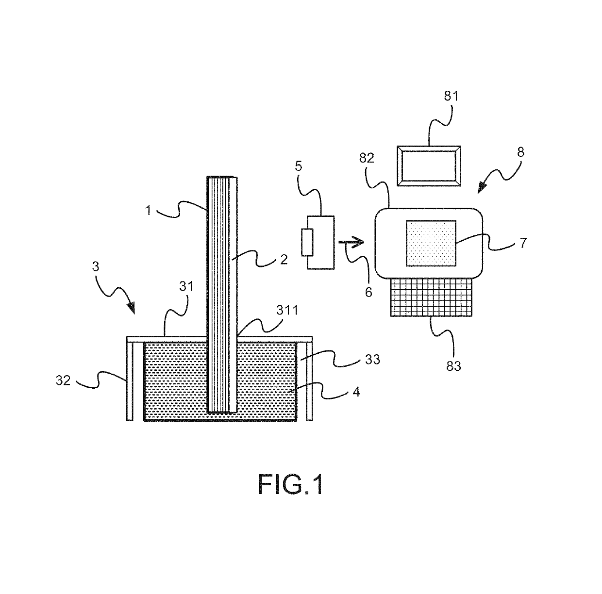
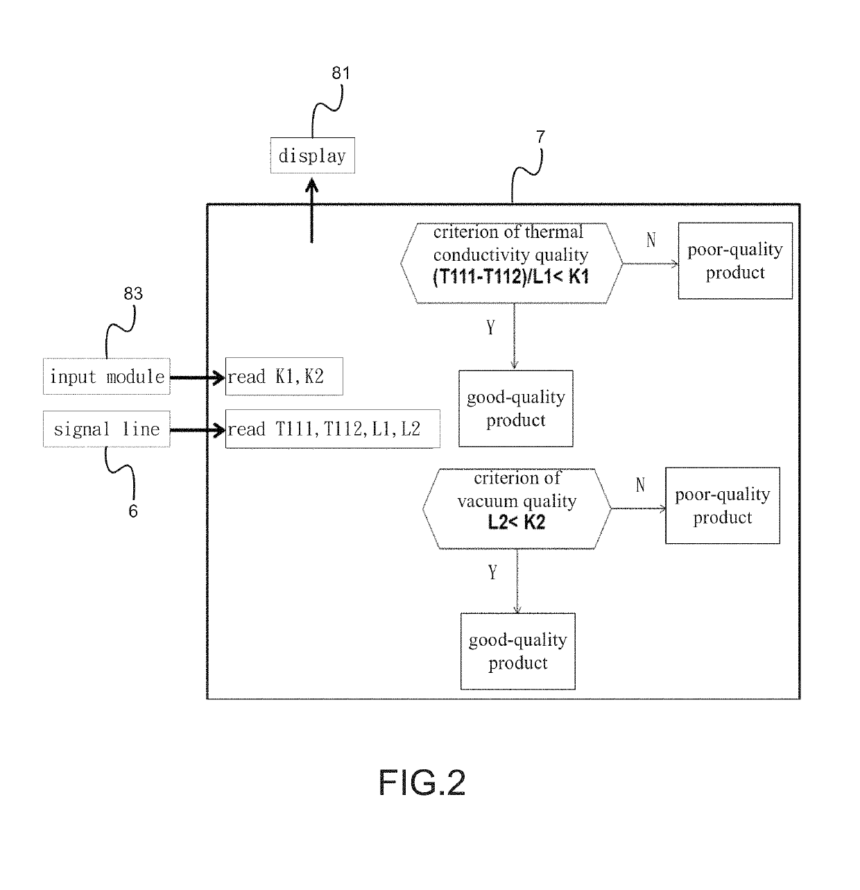
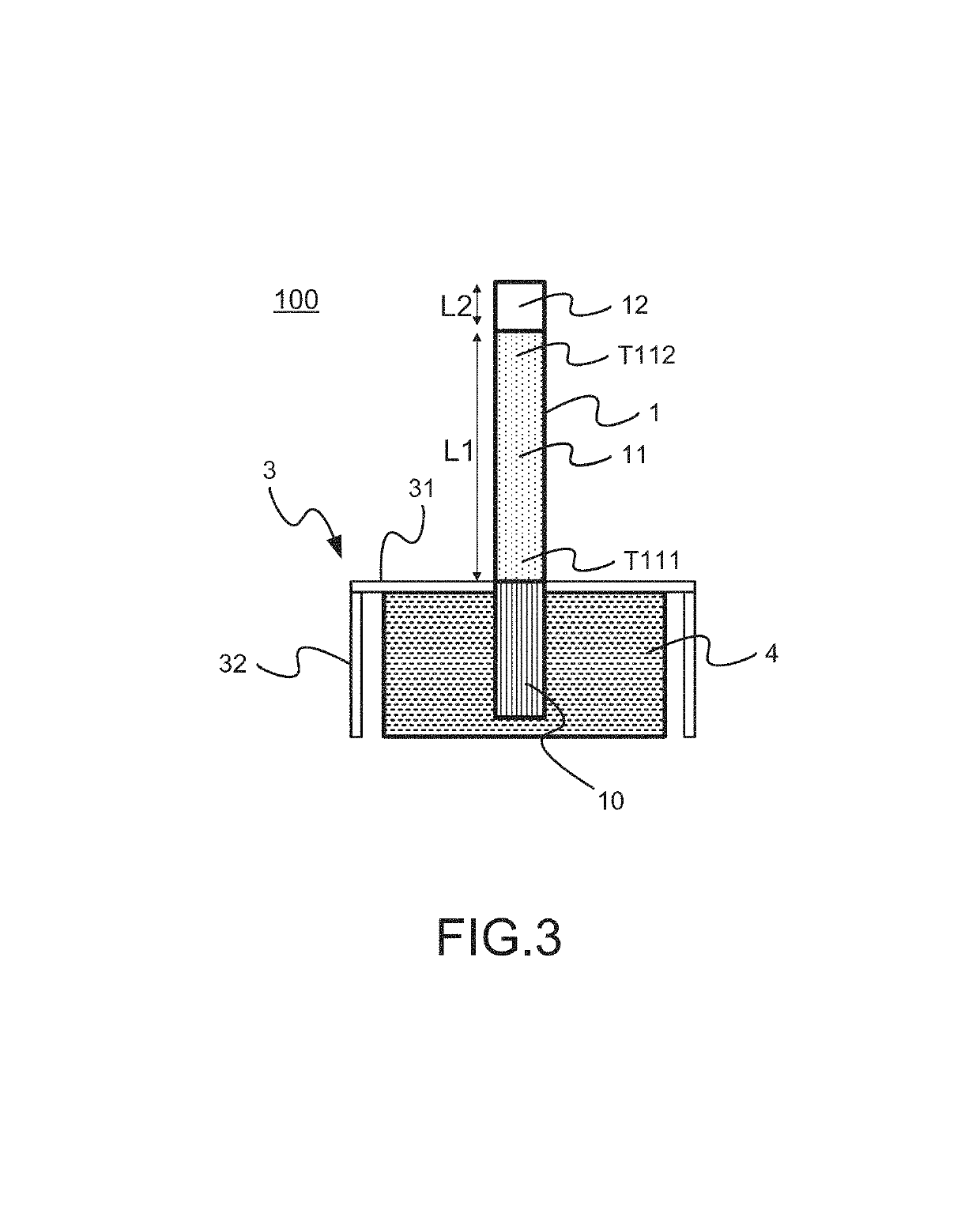
[0020]Please to FIG. 1-FIG. 5, which are a view showing a preferred embodiment according to the present invention; a flow view showing a heat-pipe quality detection program; a view showing regions of an IR thermal image; a flow view showing a method used by the present invention; and a view showing an IR thermal image of heat pipes. As shown in the figures, the present invention is an apparatus of heat pipe quality detection using an IR thermal imager. The apparatus shown in FIG. 1 comprises a heat pipe 1 to be tested, a tape 2, a fixed base 3, a heating device 4, an IR thermal imager 5, a signal line 6, a heat-pipe quality detection program 7 and an electronic device 8.

[0021]The heat pipe 1 to be tested has a closed cavity holding a working fluid. The working fluid is a fluid continuously cycling in the closed cavity and capable of changing ...


PUM

PropertyMeasurementUnit
Lengthaaaaaaaaaa
Temperatureaaaaaaaaaa
Vacuumaaaaaaaaaa

Abstract

An apparatus is provided for detecting the quality of a heat pipe. The apparatus has an infrared (IR) thermal imager bound with a data computing-and-analyzing program to detect thermal conductivity quality and vacuum quality of the heat pipe. An online overall detection is thus provided to quickly detect the quality of the heat pipe without damage for efficient quality control. Requirements of quality detection are met for mass production of heat pipes. The apparatus comprises the heat pipe to be tested; a tape adhered to a surface of the heat pipe; a fixed base for disposing the heat pipe; a heating device in an allocation space of the fixed base; the IR thermal imager located facing to the tape; a signal line connected to the IR thermal imager; and an electronic device connected to the IR thermal imager through the signal line.

Description

TECHNICAL FIELD OF THE INVENTION[0001]The present invention relates to an apparatus and method for detecting the quality of a heat pipe; more particularly, to obtaining the apparatus having an infrared (IR) thermal imager bound with a data computing-and-analyzing program to detect thermal conductivity quality and vacuum quality of the heat pipe, where an online overall detection is thus provided to quickly detect the quality of the heat pipe without damage for efficient quality control and meeting requirements of quality detection for mass production of heat pipes.DESCRIPTION OF THE RELATED ARTS[0002]Heat pipe is a most common high-efficiency thermally conductive (not heat-dissipating) device used in modern electronic products for heat dissipation.[0003]Some prior arts exist: A prior art discloses a method of detecting temperature of a heat pipe through an IR thermal image, which uses the IR thermal image to detecting the temperature of the heat pipe. Another prior art discloses a d...

Claims


Application Information

Patent Timeline
IPC IPC(8): F28F19/00G01J5/02G01J5/06F28F99/00F28F3/00G01J5/00
CPCF28F99/00G01J5/06G01J5/025G01J2005/0077F28F2245/06F28F2275/025F28F2200/005F28D15/02G01N25/18
Inventor LI, HENG-YIHUANG, TSAIR-FUHLEE, HOW-MINGKUO, PO-HSIUCHEN, YU-REN
Owner INST NUCLEAR ENERGY RES ROCAEC
Why Eureka
Try Eureka