Control apparatus for vehicle

a technology for controlling apparatus and vehicles, applied in the direction of electric control, combustion air/fuel air treatment, braking system, etc., can solve problems such as deteriorating the drivability of vehicles, and achieve the effect of suppressing the extent of us

Active Publication Date: 2019-06-04
TOYOTA JIDOSHA KK
View PDF32 Cites 0 Cited by
  • Summary
  • Abstract
  • Description
  • Claims
  • Application Information

AI Technical Summary

Benefits of technology

[0010]The present invention is made in view of the foregoing problems, and an object of the present invention is to suppress vibrations due to excessive engine torque when a vehicle running mode returns back to a valve operation running from a valve stop inertial running.
[0019]According to the third aspect, since the pressure of the intake passage section can be reduced by controlling the vacuum switching valve, the present invention can obtain the desired effect with a simple structure.
[0021]According to the fourth aspect, since the pressure of the intake passage section is controlled to be below the predetermined value smaller than the atmospheric pressure, it is possible to suppress the extent in use of the negative pressure of the vacuum pump through the intake passage by setting this predetermined value properly.

Problems solved by technology

As a result, excessive engine torque in response to an acceleration requirement through an accelerator pedal is rapidly generated to generate vibrations, possibly deteriorating drivability of a vehicle.

Method used


Image

  • Control apparatus for vehicle
  • Control apparatus for vehicle
  • Control apparatus for vehicle

Examples


first embodiment

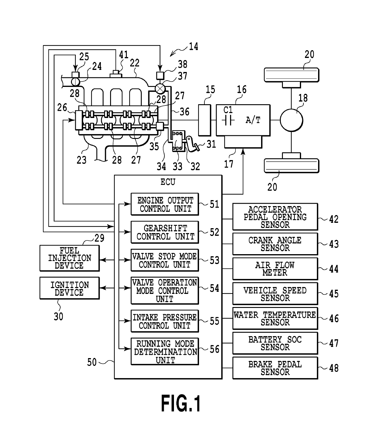
[0030]FIG. 1 is a functional block diagram illustrating the schematic configuration of a vehicle 10 according to the present invention. In FIG. 1, the vehicle 10 includes an engine 14 having a plurality of cylinders, and an automatic transmission 16. Power of the engine 10 as a driving power source is transmitted to left and right driving wheels 20 through the automatic transmission 16 and a differential gear device 18. A power transmission device 15 such as a damper device and a torque converter is provided between the engine 14 and the automatic transmission 16. A motor generator operable as the driving power source may be additionally provided between the engine 14 and the automatic transmission 16.

[0031]The engine 14 is an internal combustion engine that generates power by combustion of fuel. The engine 14 is a gasoline engine of an in-line four-cylinder, but the number of cylinders in the engine 14 may be set to any number, and the engine 14 may use fuel of a different kind lik...

second embodiment

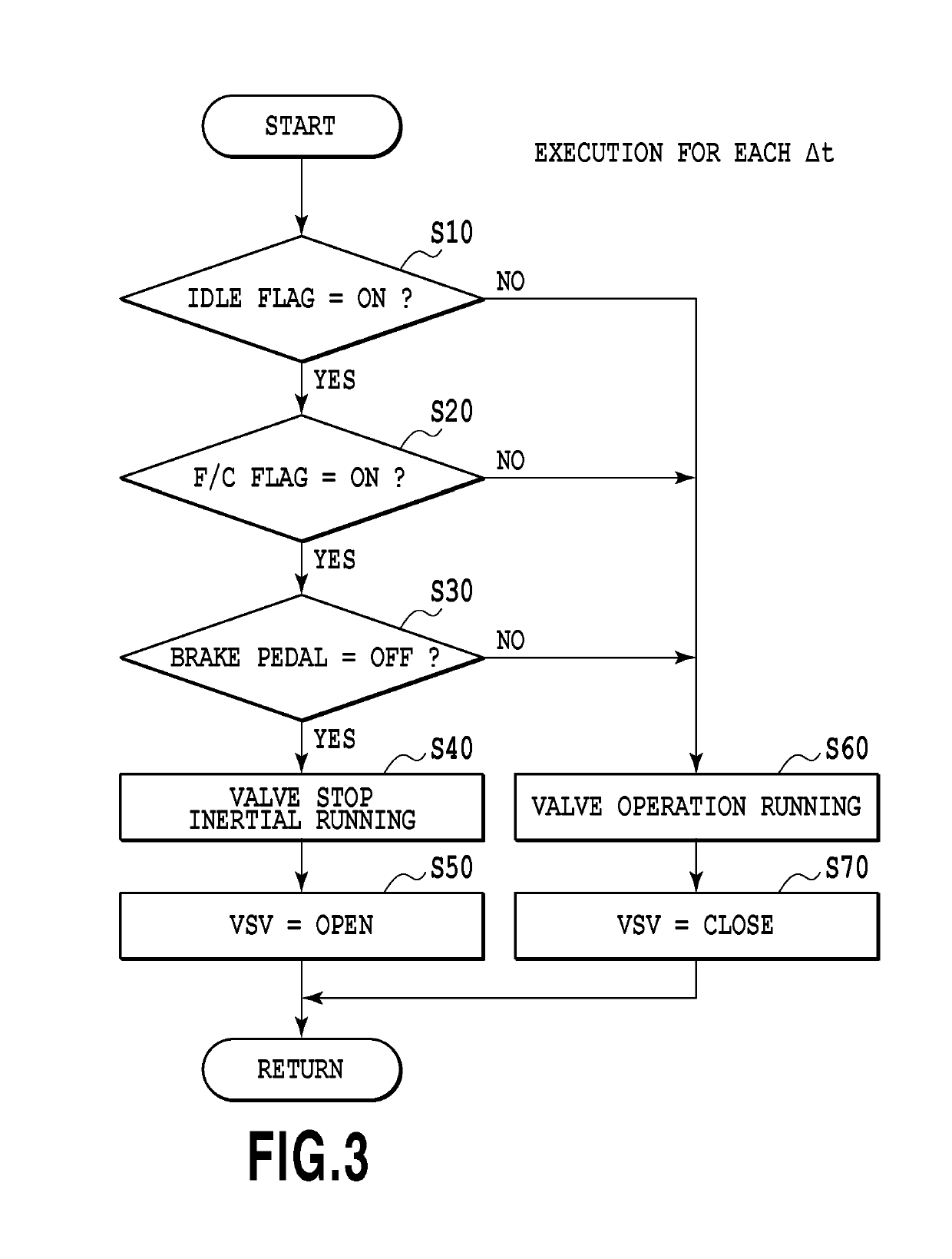
[0075]FIG. 5 is a flow chart explaining the running mode selection control to be executed in the ECU 50 according to the The running mode selection control is repeatedly executed in a predetermined cycle time At on a condition that a not shown power switch is on.

[0076]In FIG. 5, first, the ECU 50 determines whether a predetermined idle flag is on (step S110), determines whether a predetermined fuel cut flag is on (step S120), and next, determines whether the brake pedal 31 is released (step S130). The processes in step S110 to step S130 are the same as those in step S10 to step S30 in the first embodiment as described above. If yes in all of step S110 to step S130 (that is, in a case where the idle flag and the fuel cut flag are on, and the brake pedal 31 is released), the process goes to step S140.

[0077]If yes in all of step S110 to step S130, that is, if the idle condition and the fuel cut condition are satisfied and the depressing pressure of the brake pedal 31 is at the thresho...


PUM


Abstract

A vehicle having a valve stop mode control unit configured such that an intake valve and an exhaust valve are stopped in a closed state during rotation of an output shaft, supply of fuel to an engine is stopped, a clutch is made to be in an engaged state, and pistons are driven by rotational forces from driving wheels through the output shaft. When there is a request for valve stop inertial running, a negative pressure is supplied to an intake passage by a vacuum pump.

Description

CROSS-REFERENCES TO RELATED APPLICATIONS[0001]This application claims the benefit of Japanese Patent Application No. 2015-137296, filed Jul. 8, 2015, which is hereby incorporated by reference wherein in its entirety.BACKGROUND OF THE INVENTION[0002]Field of the Invention[0003]The present invention relates to a control apparatus for a vehicle, and particularly, to an apparatus applied to an engine provided with a valve operation mechanism that can stop an intake valve and an exhaust valve in a closed state during rotation of an output shaft of the engine.[0004]Description of the Related Art[0005]There is well known a valve operation mechanism that can stop an intake valve and an exhaust valve in a closed state during rotation of an output shaft of an engine. In the engine provided with this type of valve operation mechanism, in a state of connecting the engine and driving wheels with engagement of a clutch, an operation of the intake valve and an operation of the exhaust valve of the...

Claims


Application Information

Patent Timeline
Patent Type & Authority Patents(United States)
IPC IPC(8): F02D13/02B60T13/46B60T13/66F02D13/04B60T13/57B60T17/02F02D41/00F02D41/12F02D29/02F02D41/02F02D41/04
CPCF02D13/04B60T13/46B60T13/662B60T17/02F02D13/0207F02D29/02F02D41/022F02D41/12F02D41/123F02D41/0005Y02T10/42F02D41/042F02D2041/001F02D2250/41B60W10/02B60W10/06B60W30/18072B60W2030/1809B60W2710/021B60W2710/06F02D13/08F02D17/04F02M35/10229Y02T10/40
Inventor NISHIDA, HIDEYUKI
Owner TOYOTA JIDOSHA KK
Why Eureka
Try Eureka