Implementing a constant in FPGA code

a constant and fpga code technology, applied in the field of implementing constants in fpga code, can solve the problems of high demands on even modern computing nodes, dynamic models that are virtually impossible to achieve in practice now with cpu-based simulations, and the complexity of simulated environment models can become ever more precise and complex, etc., to achieve easy and efficient generation of fpga code, easy and efficient use, and high degree of freedom from errors

Active Publication Date: 2019-06-11
DSPACE DIGITAL SIGNAL PROCESSING & CONTROL ENG
View PDF8 Cites 1 Cited by
  • Summary
  • Abstract
  • Description
  • Claims
  • Application Information

AI Technical Summary

Benefits of technology

[0013]It is therefore an object of the present invention to provide a method, a data processing device, a computer program product, and a digital storage medium with control signals that are read out electronically that allow easy and efficient generation of FPGA code, that achieve a high degree of freedom from errors in the creation of FPGA code, and that allow easy and efficient use of the FPGA code for development, in particular calibration. The invention specifies a method, a data processing device, a computer program product, and a digital storage medium with control signals that are read out electronically that allow easy and efficient development, in particular calibration of FPGA code.

Problems solved by technology

Real-time simulations of complex, dynamic models place high demands on even modern computing nodes due to the tight time constraints.
These are virtually impossible to achieve in practice now with CPU-based simulations.
Hence the simulated environment models can become ever more precise and complex.
Due to increasing requirements for precision, the models of controlled systems are becoming increasingly complex, and thus also difficult to manage.
Thus no option exists for adjusting signals that have been placed on the FPGA.
Nonetheless, the process of calibration and debugging is made more difficult by the constants, since changing the signal values of the constants necessitates the generation of new FPGA code each time.
Disadvantages with respect to the performance of the FPGA model as well as the utilization of resources ensue here, however, because of the implementation of the variables with modifiable values as FPGA code.
Different implementations, for example an FPGA model using variables with modifiable values for calibration and debugging, and an FPGA model using constants with static signal values for the release, entail the disadvantage that the FPGA model must be changed for the transition to release, which is error-prone.
Moreover, differences with regard to performance may result from the different modeling, with the result that errors may at times go undetected or may not occur until release of the FPGA code.

Method used


Image

  • Implementing a constant in FPGA code
  • Implementing a constant in FPGA code
  • Implementing a constant in FPGA code

Examples


Embodiment Construction

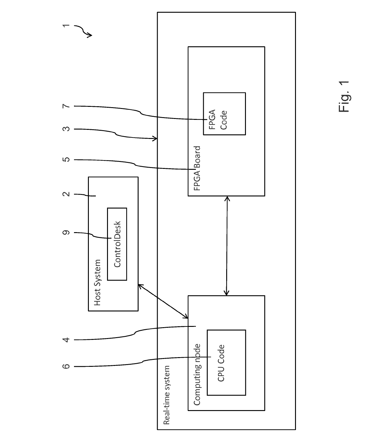
[0054]FIG. 1 shows a configuration according to the invention of a data processing system 1 with a control computer 2, here also labeled as host system, and a real-time system 3. The real-time system 3 is connected to the control computer 2 through a network connection that is not explicitly shown.

[0055]The real-time system 3 comprises a computing node 4 with a CPU that is not shown, and an FPGA board 5, which in this example embodiment is a Xilinx FPGA. The real-time system 3 here is any desired data processing device upon which a CPU application is executed as CPU code 6. FPGA code 7 is executed on the FPGA board 5. The FPGA board 5 is implemented with a plurality of I / O ports 8.

[0056]Control software 9 is executed on the control computer 2; in this example embodiment it is dSPACE ControlDesk software. The ControlDesk 9 communicates with the real-time system 3 through the computing node 4, as shown in FIG. 1.

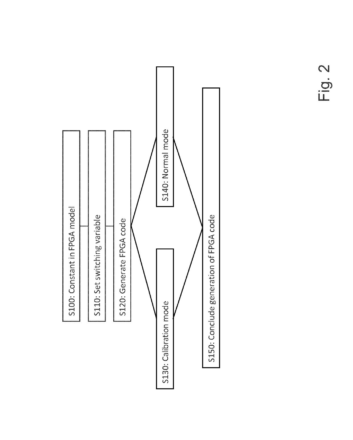
[0057]FIG. 2 shows a method for generating the FPGA code based on an FPGA...


PUM


Abstract

A method for generating FPGA code based on an FPGA model with at least one signal value that is modeled as a constant. A constant is inserted with a predefined signal value in the FPGA model. A switching variable is set in the FPGA model for switching between a normal mode and a calibration mode for the FPGA code. The FPGA code is generated for the FPGA model having the implementation of the constants in the FPGA code, wherein the implementation of the constants when the switching variable is set for normal mode includes the implementation of the constants as a fixed value in the FPGA code, and the implementation of the constants when the switching variable is set for calibration mode includes the implementation of the constants as a modifiable signal value in the FPGA code. A method for calibrating an FPGA model is also provided.

Description

[0001]This nonprovisional application claims priority under 35 U.S.C. § 119(a) to European Patent Application No. EP 14174904.4, which was filed on Jun. 30, 2014, and which is herein incorporated by reference.BACKGROUND OF THE INVENTION[0002]Field of the Invention[0003]The present invention relates to a method for generating FPGA code based on an FPGA model with at least one signal value that is modeled as a constant. In addition, the invention relates to a method for calibrating an FPGA model. The invention also relates to a computer program product with computer-implemented instructions that executes the steps of the above method after loading and execution in a suitable data processing device. In addition, the invention relates to a digital storage medium with control signals that are read out electronically and that can interact with a programmable data processing device in such a manner that the above method is carried out on the data processing device.[0004]Description of the ...

Claims


Application Information

Patent Timeline
Patent Type & Authority Patents(United States)
IPC IPC(8): G06F7/60G06F17/10G06F17/50G06F8/30
CPCG06F17/5054G06F17/5045G06F8/30G06F30/34G06F30/30G06F30/343
Inventor KALTE, HEIKOFUNKE, LUKAS
Owner DSPACE DIGITAL SIGNAL PROCESSING & CONTROL ENG
Why Eureka
Try Eureka