Hydrogen generator

A technology for generating devices and containers for hydrogen production, hydrogen, transportation and packaging

Inactive Publication Date: 2011-01-26
HITACHI MAXELL ENERGY LTD
View PDF4 Cites 2 Cited by
  • Summary
  • Abstract
  • Description
  • Claims
  • Application Information

AI Technical Summary

Problems solved by technology

[0016] However, even in the techniques disclosed in Patent Documents 3 and 4, in addition to the improvement of the hydrogen generation efficiency, there is still room for improvement regarding the structure of the container containing the hydrogen generation material.

Method used


Image

  • Hydrogen generator
  • Hydrogen generator
  • Hydrogen generator

Examples


Embodiment 1

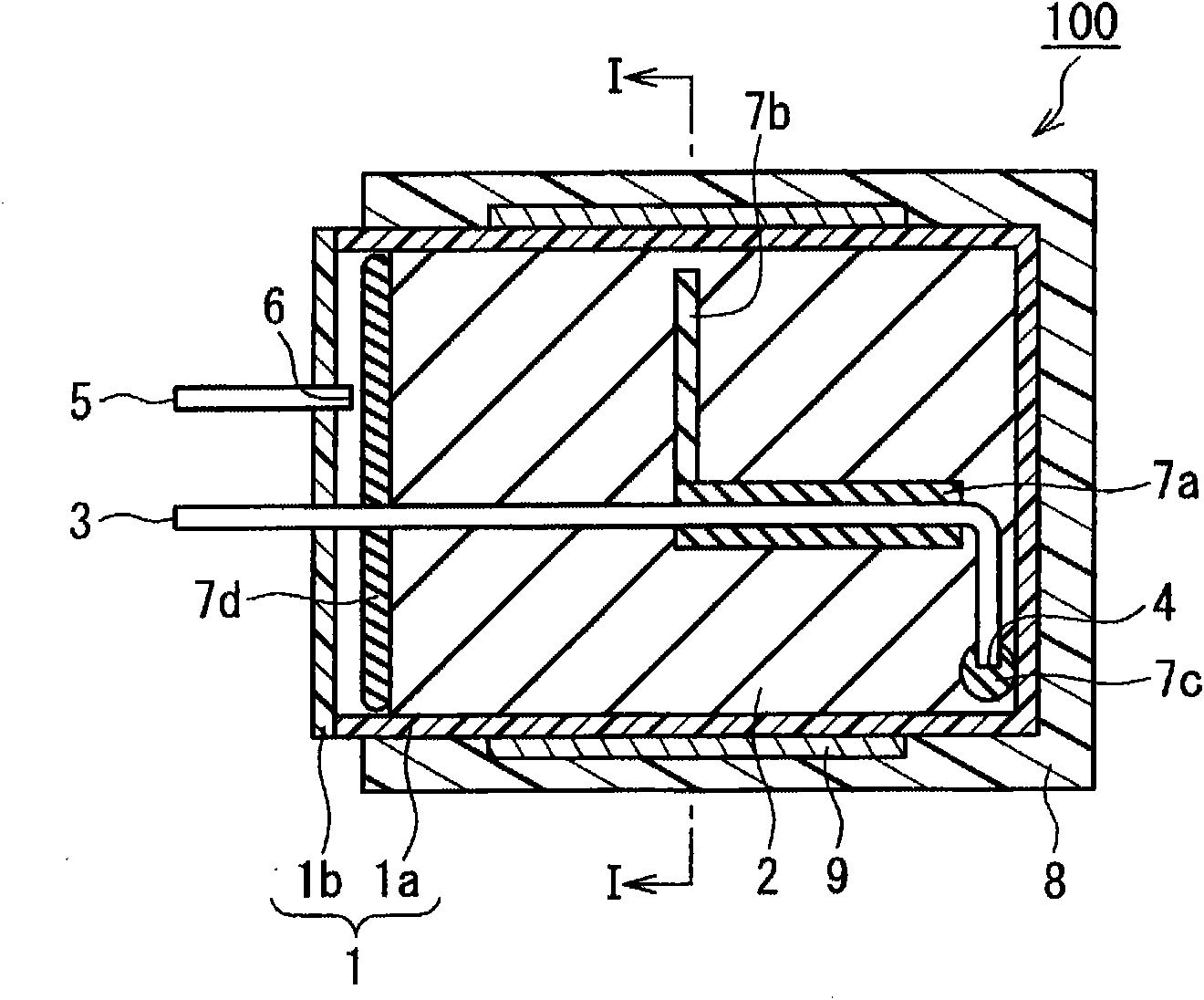
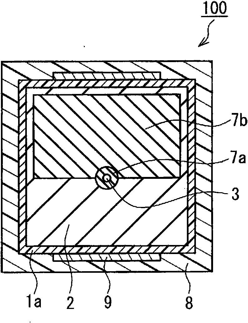
[0091] use Figure 4 Shown is a fuel cartridge 100 representing one example of a hydrogen generating device of the present invention, producing hydrogen as described. Figure 5 for, Figure 4 Sectional view in the arrow direction of line II-H. exist Figure 4 and Figure 5 in, with figure 1 and figure 2 The same symbols are assigned to the same parts, and detailed description thereof will be omitted. later mentioned Figure 6-10 the same.

[0092] Hydrogen generating material A was produced by mixing 1.0 g of aluminum powder with an average particle diameter of 6 μm as a metal material and 1.0 g of calcium oxide powder with an average particle diameter of 3 μm as an exothermic material in a mortar. In addition, hydrogen generating material B was produced by mixing 98.5 g of the above-mentioned aluminum powder as a metal material and 12.5 g of the above-mentioned calcium oxide powder as an exothermic material in a mortar.

[0093] Then, inside the container 1 (length ...

Embodiment 2~3

[0099] A hydrogen generator was produced in the same manner as in Example 1, except that absorbent cotton was disposed on the outer periphery of the water supply pipe 3 as the water absorbing material 7a under the arrangement conditions shown in Table 1. Next, hydrogen was generated in the same manner as in Example 1, and the reaction rate was measured.

Embodiment 4

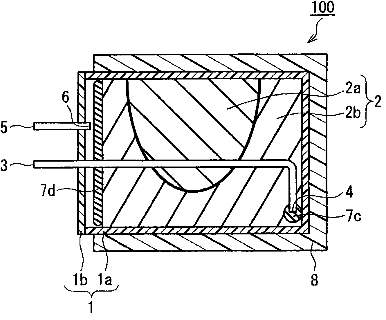
[0101] Such as Figure 6 and Figure 7 As shown, except that 0.2 g of absorbent cotton was disposed as the water-absorbing material 7b, a hydrogen generator was manufactured in the same manner as in Example 1. That is, in Figure 6 and Figure 7 In this case, the absorbent material 7b further extends from the front end of the water absorbent material 7a on the opposite side of the reference plane to the upper wall surface of the container 1, and the absorbent material 7b does not contact the wall surface. Next, hydrogen was generated in the same manner as in Example 1, and the reaction rate was measured. It should be noted, Figure 6 It is a schematic sectional view of a fuel cartridge used in this example, Figure 7 for Figure 6 Sectional view in the arrow direction of line III-III.


PUM

PropertyMeasurementUnit
particle sizeaaaaaaaaaa
thicknessaaaaaaaaaa

Abstract

A hydrogen generator comprises a container for storing a hydrogen generating material including a metallic material for generating hydrogen by the exothermic reaction with water. The container comprises a water supply pipe for supplying water into the container and a hydrogen outlet for discharging the hydrogen generated in the container to the outside of the container. The hydrogen generator is characterized in that, when the wall surface of the container which faces the hydrogen outlet is taken as a reference plane, a water supply port at the end of the water supply pipe disposed in the container is disposed near the reference plane, the water supply pipe includes a vertical portion extending from near the center of the reference plane in the direction vertical to the reference plane, and a water absorbent is disposed on the outer periphery of the vertical portion of the water supply pipe and not disposed in the portion of 15% or longer of the effective length of the vertical portion on the hydrogen outlet side.

Description

technical field [0001] The present invention relates to a hydrogen generator using a metal material that reacts with water to generate hydrogen. Background technique [0002] In recent years, with the popularization of cordless devices such as personal computers and mobile phones, secondary batteries used as power sources for such devices have been increasingly required to be smaller in size and higher in capacity. Lithium-ion secondary batteries are currently in practical use as secondary batteries that can achieve high energy density and reduced size and weight, and demand for portable power sources is increasing. However, the lithium ion secondary battery has not been able to secure a sufficient continuous use time for various kinds of applied cordless devices. [0003] Under such circumstances, a solid polymer fuel cell is exemplified as an example of a battery that can meet the above-mentioned urgent needs. A solid polymer fuel cell in which a solid polymer electrolyt...

Claims


Application Information

Patent Timeline
Patent Type & Authority Applications(China)
IPC IPC(8): C01B3/08C22C32/00H01M8/04H01M8/06H01M8/10B22F1/00B22F1/02B22F1/068B22F1/16
CPCH01M8/065H01M8/04216C01B3/065Y02E60/362B22F1/0055B22F1/02C01B3/08Y02E60/50B22F1/0007H01M8/04208Y02E60/36B22F1/068B22F1/16
Inventor 三木健中井敏浩西原昭二
Owner HITACHI MAXELL ENERGY LTD
Why Eureka
Try Eureka