Pattern matching method and apparatus

a pattern matching and apparatus technology, applied in the field of pattern matching technology, can solve the problems of reducing the automation rate of pattern matching, the failure of automatic alignment, and the operation rate of the apparatus, so as to avoid an increase in the number of template registration operations, avoid the burden of operation, and suppress the failure of pattern matching.

Active Publication Date: 2019-06-11
HITACHI HIGH-TECH CORP
View PDF14 Cites 1 Cited by
  • Summary
  • Abstract
  • Description
  • Claims
  • Application Information

AI Technical Summary

Benefits of technology

[0017]As a measure to avoid such a problem, various methods have been studied so far. For example, a method of setting a low similarity threshold is known. When a low similarity threshold is set, it is possible to suppress cases where pattern matching is determined to have failed. Meanwhile, when a low similarity threshold is set, there is an increasing risk of error detection of patterns. Thus, an operator should avoid failures of pattern matching by registering a different template image for each step.
[0026]To conclude, in the field of pattern matching, it is currently demanded to suppress failures of pattern matching and avoid an increase in the number of template registration operations. Thus, the present invention provides a pattern matching technology that can absorb changes in how patterns look and does not place a heavy operation burden on an operator.

Problems solved by technology

However, there are cases where automatic alignment fails.
Thus, a failure of the automatic alignment results in a decrease in the automation rate of the pattern matching and a decrease in the operating rate of the apparatus.
A failure of pattern matching is considered to occur because how patterns on a semiconductor wafer look changes for some reasons.
In such cases, a similarity between a search target image and a template image would decrease (a calculated similarity score would be below the threshold), resulting in a failure of the pattern matching.
Meanwhile, when a low similarity threshold is set, there is an increasing risk of error detection of patterns.
Therefore, performing an operation of registering a different template image for each step would be a great burden for an operator.
Thus, it is difficult to select a place to be registered.
Thus, the template registration operation is not easy.
However, this method would increase a burden of registering a plurality of template images.
In addition, even if registration of a plurality of template images is possible, it is still difficult to select positions for registration unless an operator fully knows how patterns will change during the manufacturing steps.
However, as CAD data is data with an extremely large volume, an investment in a facility that can handle such data would be a great burden.
In addition, there may be a case where an operator is not allowed to handle the CAD data for security reasons.
Further, another problem would arise that, for example, a new algorithm for which OPC (Optical Proximity Correction) and the like are taken into consideration should be introduced into matching between the CAD data and a real image.

Method used


Image

  • Pattern matching method and apparatus
  • Pattern matching method and apparatus
  • Pattern matching method and apparatus

Examples


Embodiment Construction

[0043]Hereinafter, embodiments of the present invention will be described with reference to the accompanying drawings. It should be noted that the embodiments of the present invention are not limited to those described below, and various modifications and variations are possible in so far as they are within the spirit and scope of the present invention.

[Summary of Pattern Matching Method in Accordance with Embodiment]

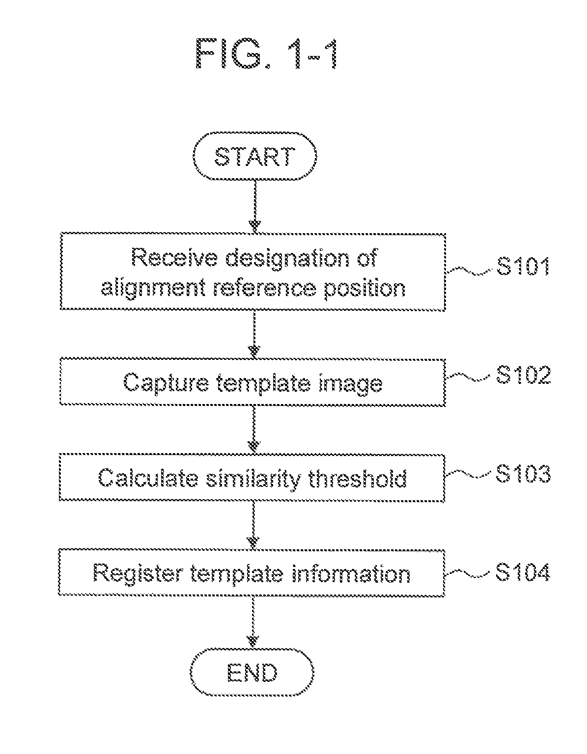
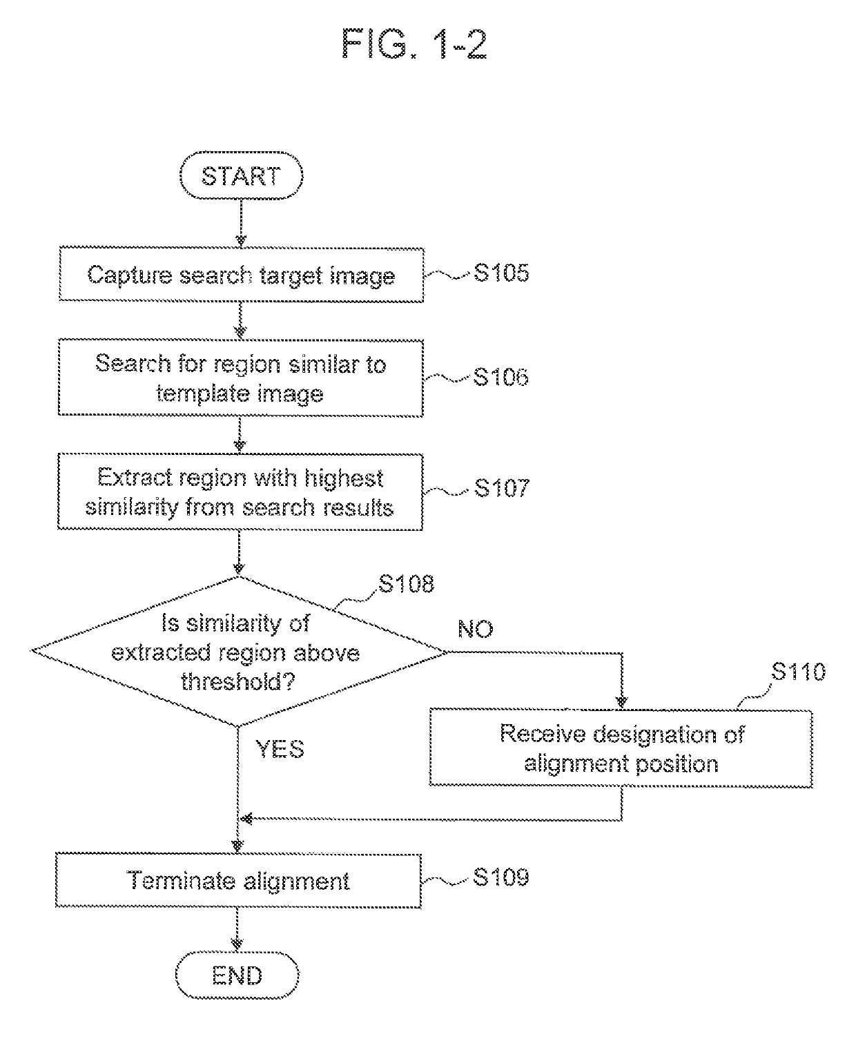
[0044]A pattern matching method in accordance with an embodiment also includes a template image registration process and a pattern matching process. The template image registration process in accordance with an embodiment provides an operator with operability that is about equal to the operability of a commonly known template registration process. Specifically, a registration process in accordance with an embodiment provides a registration process that needs no knowledge about registration of a pattern for each of a plurality of steps or a pattern deformation that would...


PUM


Abstract

When the degree of matching between patterns decreases due to a pattern fluctuation or an appearance fluctuation that has occurred during manufacturing steps, a heavy work burden would be placed on an operator. A data processing unit of a pattern matching apparatus calculates a threshold for determination of matching between a first template image and a partial region of a search target image obtained by capturing an image of the surface of a sample, on the basis of a result of evaluation of a similarity between the search target image and a second template image, the second template image having been captured in a wider range than the first template image.

Description

BACKGROUND[0001]1. Technical Field[0002]The present invention relates to a pattern matching technology. For example, the present invention relates to a pattern matching method and apparatus for identifying the position of a pattern formed on the surface of a sample.[0003]2. Background Art[0004]A pattern matching technology is known as one of the technologies used to measure or test a fine structure on the surface of a sample, such as a semiconductor circuit. The pattern matching technology is a technology of identifying the position of a pattern on the basis of a similarity between a sample image and a reference image referred to as a template.[0005]FIG. 1-1 and FIG. 1-2 slow process procedures that are typically used in pattern matching. FIG. 1-1 shows a process procedure used for registration of a template, and FIG. 1-2 shows a process procedure executed when alignment is performed using the template.[0006]A pattern registration process is started after the alignment reference pos...

Claims


Application Information

Patent Timeline
Patent Type & Authority Patents(United States)
IPC IPC(8): H04N7/18G06T7/00G06K9/00G06T7/33
CPCG06K9/00536G06T7/001G06T7/33G06T2207/30148G06T2207/10061G06F2218/12
Inventor NAKAYAMA, HIDEKISAKAMOTO, MASASHI
Owner HITACHI HIGH-TECH CORP
Why Eureka
Try Eureka