
Dual interface metal smart card with booster antenna

a metal smart card and booster technology, applied in the direction of instruments, radiating element structural forms, basic electric elements, etc., can solve the problem of useless contactless smart cards, and achieve the effect of enhancing rf transmission

Active Publication Date: 2019-06-11
COMPOSECURE LLC
View PDF19 Cites 18 Cited by
  • Summary
  • Abstract
  • Description
  • Claims
  • Application Information

AI Technical Summary

Benefits of technology

The solution enhances RF transmission and maintains a sophisticated appearance by isolating the IC module from the metal layer, ensuring effective dual interface functionality without compromising the card's appearance.

Problems solved by technology

However, several problems arise in the making of dual interface (“contactless” and “contact”) smart cards with a metal layer because of conflicting requirements.
However, any metal layer in the card interferes with radio-frequency (RF) communication signals (e.g., attenuates) between the card and the reader, and this may render the contactless smart card useless.

Method used


Image

  • Dual interface metal smart card with booster antenna
  • Dual interface metal smart card with booster antenna
  • Dual interface metal smart card with booster antenna

Examples


Embodiment Construction

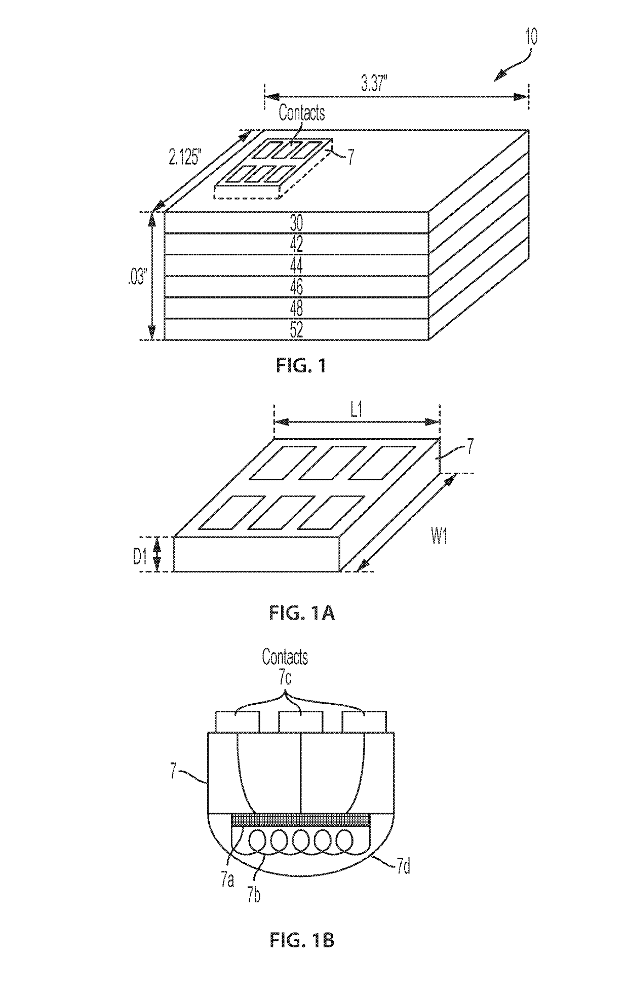
[0038]An integrated circuit (IC) module 7 having multiple contacts as shown in FIG. 1A is to be mounted in, and on, a card 10 as shown in FIG. 1 with the top surface of the IC module and its contacts generally flush with the top surface of the card. By way of example it is shown that the length, width and depth of the card may respectively be approximately 3.37 inches by 2.125 inches by 0.03 inches. For purpose of illustration and the discussion to follow, we assume, as shown in FIG. 1A, that the IC module has a depth D1, a length L1 and a width W1. Modules such as IC module 7 are commercially available, for example, from Infineon or NXP. The lateral dimensions of some of these modules were approximately 0.052 inches by 0.47 inches with a depth ranging from 0.005 inches to more than 0.025 inches. These dimensions are purely illustrative and IC modules used to practice the invention may be greater or smaller in size.

[0039]As shown in FIG. 1B, IC module 7 contains an internal micropro...


PUM


Abstract

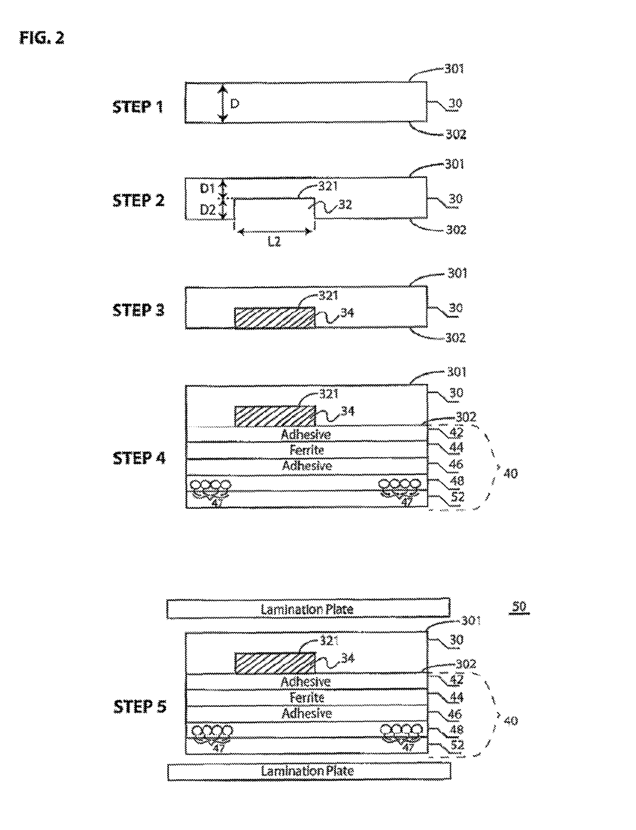
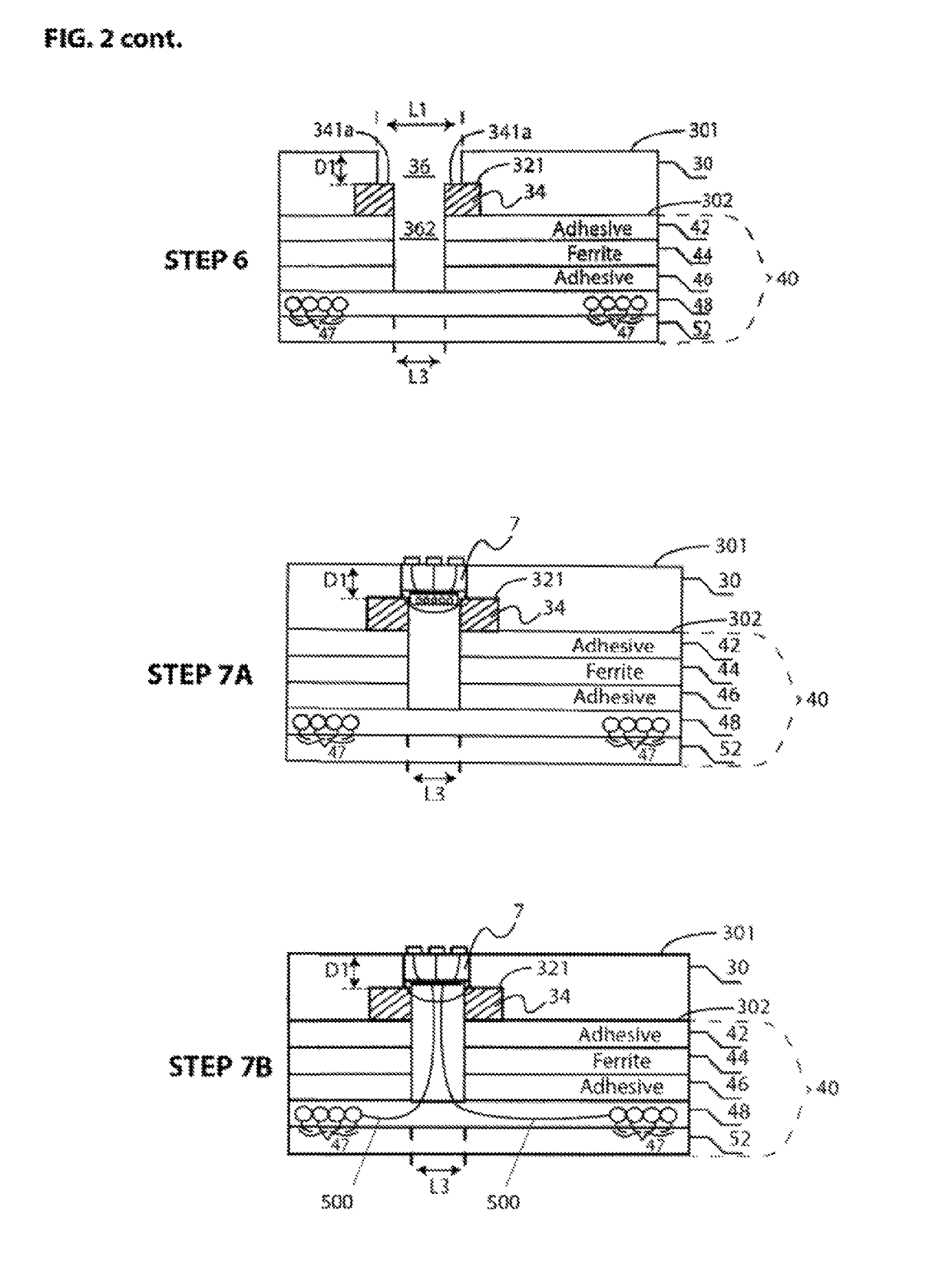
A card having a metal layer and an opening or cut-out region in the metal layer, with a dual-interface integrated circuit (IC) module disposed in the opening or cut-out region. A ferrite layer is disposed below the metal layer and a booster antenna is attached to the ferrite layer. A vertical hole extends beneath the IC module through the ferrite layer. The booster antenna may be physically connected to the IC module or may be configured to inductively couple to the IC module. In some embodiments, the IC may be disposed in or on a non-conductive plug disposed within the opening or cut-out region, or the vertical hole may have a non-conductive lining, or a connector may be disposed between the booster antenna and the IC module in the vertical hole.

Description

CROSS REFERENCE TO RELATED APPLICATIONS[0001]This application is a CIP of U.S. application Ser. No. 15 / 742,813, filed Jan. 8, 2018, titled METAL SMART CARD WITH DUAL INTERFACE CAPABILITY, which is a national phase of PCT Application Ser. No. PCT / US2015 / 039535, filed Jul. 8, 2015, both of which are incorporated by reference herein in their entireties.BACKGROUND OF THE INVENTION[0002]Smart cards are highly desirable and are in wide use, including: in payment and ticketing applications, such as mass transit and motorway tolls; in personal identification and entitlement schemes on regional, national, and international levels; in citizen cards; in drivers' licenses; in patient card schemes; and in biometric passports to enhance security for international travel.[0003]A smart card is a card that includes embedded electronic circuitry such as an integrated circuit (IC) chip that connects or couples to a card reader with direct physical contact and / or with a remote contactless radio frequen...

Claims


Application Information

Patent Timeline
Patent Type & Authority Patents(United States)
IPC IPC(8): H01Q1/22H01L23/66G06K19/077H01Q1/38
CPCG06K19/07794H01L23/66H01Q1/2225H01Q1/38H01Q1/2216H01L2223/6677
Inventor LOWEHERSLOW, JOHNDASILVA, LUISNESTER, BRIAN
Owner COMPOSECURE LLC
Learn More