Electrical connectors having a bent main body for electrical connection between a housing and a support, and being disposed as a grid array or network

a technology of electrical connection and main body, which is applied in the direction of coupling device connection, contact member manufacturing, electrical apparatus, etc., can solve the problems of degrading the mechanical and/or electrical functions of the package, unable to withstand the great side differential movement between the package and the microelectronic support, and unable to connect through the periphery of the package, etc., to achieve simple and robust design, moderate cost, and easy calculation

Active Publication Date: 2019-06-11
COMMISSARIAT A LENERGIE ATOMIQUE ET AUX ENERGIES ALTERNATIVES
View PDF34 Cites 0 Cited by
  • Summary
  • Abstract
  • Description
  • Claims
  • Application Information

AI Technical Summary

Benefits of technology

[0020]Consequently, there is a need for providing an alternative solution of a connector being advantageously flexible between a package and a support, in particular a printed circuit, such a connector being in particular of a simple design and robust, of a moderate cost, readily calculatable, and able to meet electrical, mechanical and thermal functions assigned thereto as well as compensate for non-flatness or non-coplanarity defects of the package and / or the support.
[0023]By virtue of the invention, it s possible to provide a new connector type meeting the above-discussed needs and requirements. In addition, it is worth of note that the connector according to the invention can enable a great dimension package to be connected to the support which is in particular microelectronic. Indeed, with the principle of the connector according to the invention, it is possible to achieve both the desired, even relatively low, stiffness, of the connector in the direction of the plane of the support or of the package and a relatively large displacement, for example of about one hundred microns or more, between top and bottom of the connector in the direction of the plane of the support or the package. Thereby, it can be possible to dimension the connector to adjust independently stiffnesses in the directions normal and parallel to the package and the support.
[0028]Furthermore, the main body of the connector can be elastic.
[0046]Advantageously, the arrangement of the electrical connectors along a same general direction orthogonal to the device, with different orientations, enables stresses (or deformations) applied to the device to be managed. In particular, the different orientations of these connectors can be applied between adjacent connectors so as to create an overall isotropic stress in the device: the rigidity along the axis x of a first connector is equal to the rigidity along the axis y of a second connector, adjacent to the first connector and oriented at 90° and the rigidity along the axis y of the first connector is equal to the rigidity along the axis x of the second connector. Thus, the overall rigidity of both these connectors is identical along the axes x and y, enabling an overall isotropic behaviour of the device to be achieved.

Problems solved by technology

Hence, the connection through the periphery of the package becomes difficult, or even impossible, and it is generally preferred a connection through a grid array (possibly incomplete), that is an array or a grid, of connectors placed on most of one of the faces of the package.
However, the drawback with using such metal balls is generally that they are not able to withstand great side differential movements between the package and the microelectronic support, without degrading their mechanical and / or electrical functions.
However, the drawbacks of these metal columns are that they have a high manufacturing cost and they are complicated to produce, in particular in case of the presence of an inner or outer structure, or to be installed to the package.
Moreover, the amplitude of the side movements (due to the differential expansions between the package and the microelectronic support) they can withstand without being deteriorated is limited, even if higher than that achieved with the metal balls.
This manual step, as well as all the related handlings, are delicate because of the plasticity of the columns which are deformed whatever the blow is.
If these springs enable very strong amplitude impacts to be withstood, however they have too high an inductance, induce too much insertion losses and cannot be used for high frequency signals, for example in the order of 10 GHz.
On the other hand, there are impractical to assemble to the package and to the microelectronic support, since the spires at the ends are not coplanar.

Method used


Image

  • Electrical connectors having a bent main body for electrical connection between a housing and a support, and being disposed as a grid array or network
  • Electrical connectors having a bent main body for electrical connection between a housing and a support, and being disposed as a grid array or network
  • Electrical connectors having a bent main body for electrical connection between a housing and a support, and being disposed as a grid array or network

Examples


Embodiment Construction

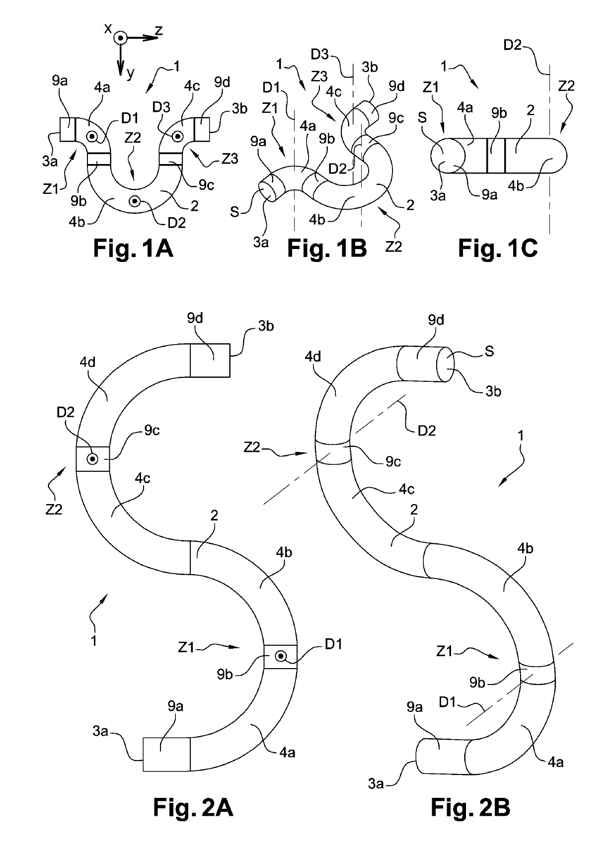
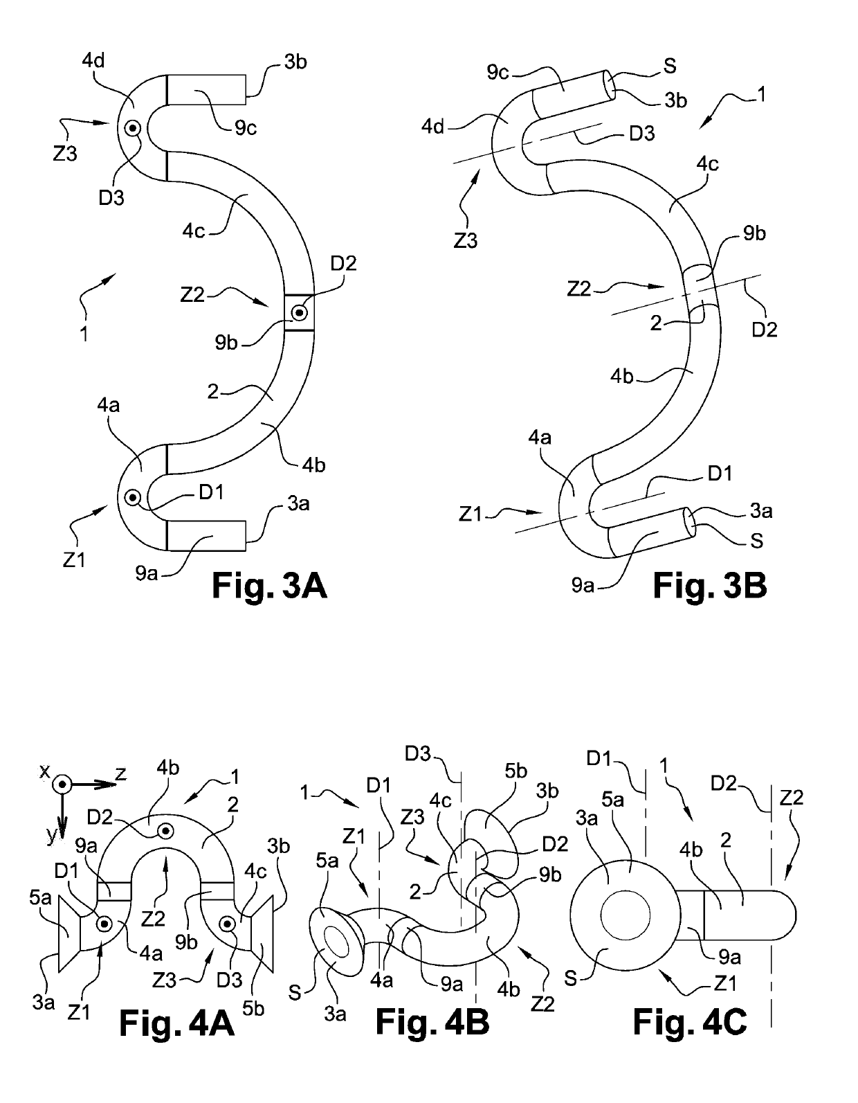
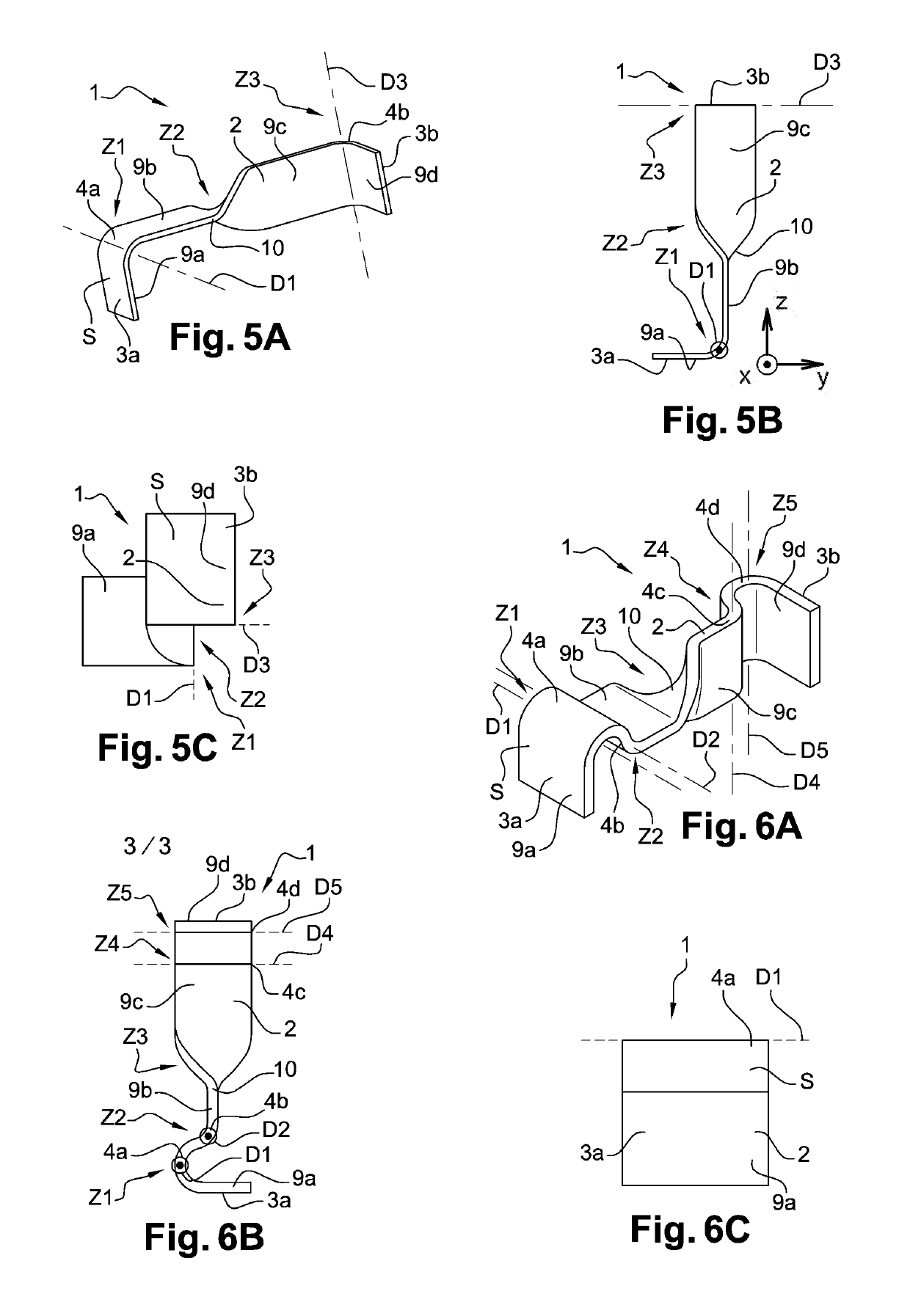
[0077]In reference to FIG. 1A to 8C, eight exemplary embodiments of connectors 1 in accordance with the invention have, been represented. Such connectors 1 are in particular intended to allow a microelectronic package and a microelectronic support, and in particular a printed circuit to be connected as a grid array.

[0078]According to a first alternative in reference to FIG. 1A to 4C, the connectors 1 can be in the form of folded metal wires.

[0079]According to a second alternative in reference to FIG. 5A to 7C, the connectors 1 can be in the form of folded metal strips.

[0080]Finally, according to a third alternative in reference to FIG. 8A to 8C, the connector 1 can be in the form of a plate, and in particular in the form of a folded metal sheet.

[0081]In all these exemplary embodiments of connectors 1 in accordance with the invention in reference to FIG. 1A to 8C, each connector 1 includes a main body 2 provided with a first end 3a for being connected with the microelectronic package...


PUM


Abstract

An electrical connector allowing a connection between two substantially facing electrical contacts respectively pertaining to a housing and a support, and including a main body including a first end for secure connection thereof to the housing and a second end for secure connection thereof to the support, the main body being bent in at least one bending area.

Description

TECHNICAL FIELD[0001]The present invention relates to the general field of connector technology, in particular for microelectronics, and more specifically to the field of mechanical and electrical connection means between a package, which is in particular microelectronic can be of a relatively great dimension, and a support, which is in particular microelectronic and can be for example a printed circuit board. Specifically, the invention is concerned with such connection means provided to withstand mechanical deformations without degrading their functions.[0002]The invention finds for example favoured applications in the fields of computer science, telephony, avionics, spatial electronics and automotive electronics, so-called airborne electronics, as well as for most of nomadic electronic objects, among other things.[0003]It thus provides a connector for a grid array connection between a package and a support, a device including a plurality of such connectors arranged as a grid arra...

Claims


Application Information

Patent Timeline
Patent Type & Authority Patents(United States)
IPC IPC(8): H01R12/52H01R13/24H01R43/16H01L23/00
CPCH01R12/52H01L24/67H01R43/16H01R13/2435H01L2224/67
Inventor DE CRECY, FRANCOISDIEM, BERNARDFERRANDON, CHRISTINEHILT, THIERRY
Owner COMMISSARIAT A LENERGIE ATOMIQUE ET AUX ENERGIES ALTERNATIVES
Why Eureka
Try Eureka