Transmission for a hybrid vehicle, drive train for a hybrid vehicle having such a transmission, and method for starting up a hybrid vehicle

a technology for hybrid vehicles and transmissions, which is applied in the direction of mechanical equipment, transportation and packaging, and transmissions. it can solve the problems of increasing the axial structural length affecting the interior space of the hybrid vehicle, and limiting the structural space. it promotes the compact design of the transmission, promotes the short axial construction of the transmission, and promotes the effect of short axial structure length

Active Publication Date: 2019-07-16
ZF FRIEDRICHSHAFEN AG
View PDF16 Cites 2 Cited by
  • Summary
  • Abstract
  • Description
  • Claims
  • Application Information

AI Technical Summary

Benefits of technology

[0015]Such an arrangement of the second and third shift elements is suitable in particular for use in a transmission for a drivetrain which is oriented substantially parallel to the direction of travel of the motor vehicle. This is because, owing to the arrangement of the second and third shift elements axially between the electric machine and the first planetary gear set, the transmission remains radially compact, whereby a central tunnel of the motor vehicle can likewise be of compact design. The space availability in the interior compartment of the motor vehicle is thus improved. By the arrangement according to the invention of the second and third shift elements, it is furthermore possible for the axial structural length of the transmission to be kept short, specifically at the expense of the effective diameter of the second shift element. The central tunnel of the motor vehicle can thus be narrowed at an early point, whereby, likewise, the space availability in the interior compartment of the motor vehicle is improved.
[0031]In a method for launching the hybrid vehicle, proceeding from a standstill state of the hybrid vehicle with the internal combustion engine running, the separating clutch and the second shift element are closed if they are not already closed. When the separating clutch and the second shift element are closed, then for launching in the forward direction the first shift element is transferred from the open state into a slipping state, and for launching in the reverse direction the fifth shift element is transferred from the open state into a slipping state. Here, torque is transmitted from the drive shaft to the output shaft, wherein the slipping operation of the first or of the fifth shift element respectively permits a rotational speed equalization. The first and fifth shift elements thus serve as launch elements, which are arranged within the transmission. The first and fifth shift elements should therefore be formed as frictionally locking shift elements, which permit such slipping operation. The separating clutch thus does not serve as a launch element, and may therefore also be formed as a positively locking shift element. Owing to the arrangement of the launch elements within the transmission, the structural space requirement of the transmission can be further reduced. Since the second shift element is formed as a positively locking shift element, the second shift element cannot serve as launch element. The method for launching thus relates to the transmission described above. This is because a second shift element formed as a frictionally locking shift element would be preferred as a launch element, because this is closed both in the first forward gear ratio and in the reverse gear ratio, and could thus serve as a launch element regardless of the direction of travel of the hybrid vehicle.

Problems solved by technology

Transmissions for hybrid vehicles commonly have an increased structural space requirement owing to the electric machine.
In the case of a drivetrain parallel to the direction of travel, the space availability in the interior compartment of the hybrid vehicle is impaired by the increased axial structural length.
This is undesirable.
In the case of a drivetrain transverse to the direction of travel, the structural space is greatly limited, because the assembly composed of internal combustion engine, electric machine and transmission is normally arranged between the longitudinal members and the wheels of the hybrid vehicle.
Frictionally locking shift elements, such as for example multiplate brakes, impair the efficiency, because they generate drag losses in the open state.
In the case of the motor vehicle transmission known in the prior art, such drag losses arise to a particularly great extent at the second brake, because said second brake must be designed with a particularly large effective surface owing to the high torque loading, and because said second brake is closed only in the first forward gear ratio and in the reverse gear ratio.

Method used


Image

  • Transmission for a hybrid vehicle, drive train for a hybrid vehicle having such a transmission, and method for starting up a hybrid vehicle
  • Transmission for a hybrid vehicle, drive train for a hybrid vehicle having such a transmission, and method for starting up a hybrid vehicle
  • Transmission for a hybrid vehicle, drive train for a hybrid vehicle having such a transmission, and method for starting up a hybrid vehicle

Examples


first embodiment

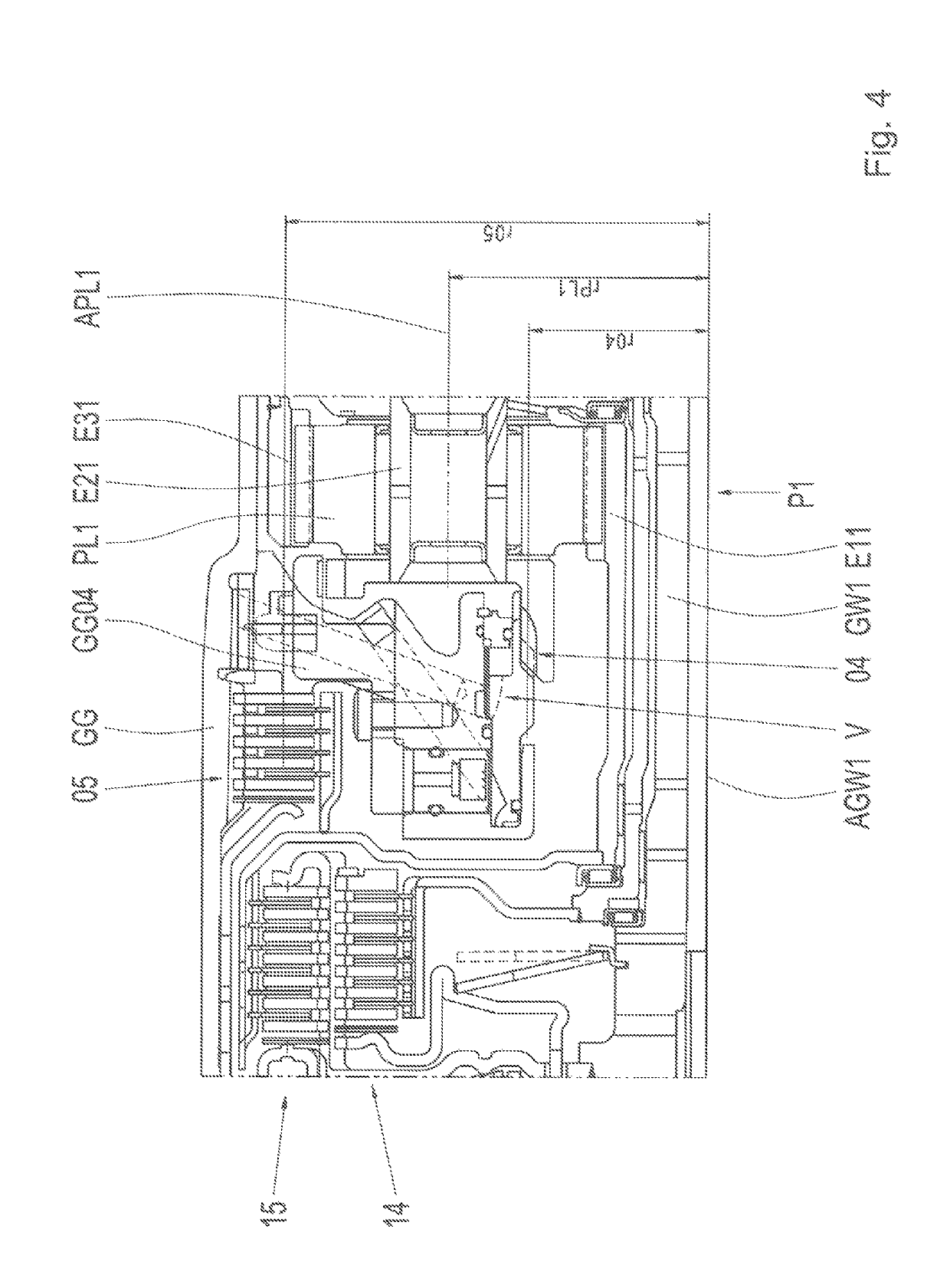
[0050]FIG. 4 shows a sectional illustration of a part of the transmission G as per a The first planetary gear set P1 is formed as a minus gear set, wherein a dog-clutch toothing is connected to the carrier of the first planetary gear set P1. Said dog-clutch toothing is a constituent part of the second shift element 04. The device V for actuating the second shift element 04, which device is formed as a hydraulic device, is fastened to the holding element GG04. A predominant part of said device V is arranged radially within the third shift element 05. The supply of hydraulic fluid to the device V runs in this case through ducts within the holding element GG04. The device V also has a means for detecting the position of the dog-clutch shift element 04, which means determine the axial position at that end of the displaceable element which is situated opposite the dog-clutch toothing.

second embodiment

[0051]FIG. 5 shows a sectional illustration of a part of the transmission G as per a The device V for actuating the second shift element 04, which device is formed as an electromagnetic device, is fastened to the holding element GG04. The electromagnet, illustrated by hatching, is designed such that, when electrically energized, it attracts an armature counter to a spring force, wherein the armature is fixedly connected to the axially displaceable element of the dog-clutch shift element 04. In the electrically deenergized state, the dog-clutch shift element 04 is opened by the spring force. The device V is arranged predominantly radially within the third shift element 05.

third embodiment

[0052]FIG. 6 shows a sectional illustration of a part of the transmission G as per a In this, the device V for actuating the second shift element 04 is formed as a hydraulic actuating device, which is designed to hydraulically close and hydraulically open the second shift element 04. Radially within the device V, the holding element GG04 has an abutment against which an axial bearing AL is supported. The axial bearing AL is formed as a rolling bearing and is designed to transmit forces acting in an axial direction from the first planetary gear set P1 to the holding element GG04. The first planetary gear set P1 is thus supported via the axial bearing AL on the holding element GG04 in the presence of a load acting towards the left in the figure. In the presence of a load acting towards the right in the figure, the first planetary gear set P1 is supported on a bearing arrangement on the transmission housing; this is not illustrated in FIG. 6. Radially within the device V, the holding ...


PUM


Abstract

A transmission (G) for a hybrid vehicle includes a drive shaft (GW1), an output shaft (GW2), three planetary gear sets (P1, P2, P3), an electric motor (EM) with a rotationally fixed stator (S) and with a rotatable rotor (R), and five shift elements (03, 04, 05, 14, 15). Six forward gear ratios (1 to 6) and one reverse gear ratio (R1) are formable through selective pairwise closure of the five shift elements.

Description

FIELD OF THE INVENTION[0001]The invention relates generally to a transmission for a hybrid vehicle, to a drivetrain for a hybrid vehicle having a transmission of said type, and to a method for launching a hybrid vehicle.BACKGROUND[0002]The applicant's patent application DE 199 12 480 A1 describes an automatically shiftable motor vehicle transmission having three single-carrier planetary gear sets, three brakes and two clutches for the shifting of six forward gear ratios and one reverse gear ratio, and having a drive shaft and an output shaft. The drive shaft is connected directly to the sun gear of the second planetary gear set, and is connectable by the first clutch to the sun gear of the first planetary gear set and by the second clutch to the carrier of the first planetary gear set. The sun gear of the first planetary gear set is connectable by the first brake, the carrier of the first planetary gear set is connectable by the second brake, and the sun gear of the third planetary ...

Claims


Application Information

Patent Timeline
Patent Type & Authority Patents(United States)
IPC IPC(8): F16H3/66B60K6/48B60K6/365
CPCF16H3/66B60K6/365B60K6/48F16H2200/2094F16H2200/201F16H2200/2043F16H2200/2064F16H2200/0052
Inventor BECK, STEFANBREHMER, MARTINFUHRER, KIMGEIGER, ANDREASHORN, MATTHIASRIEDISSER, THOMAS
Owner ZF FRIEDRICHSHAFEN AG
Why Eureka
Try Eureka