
Adaptive optimization for dynamic room pressurization control

a dynamic room and control technology, applied in fluid pressure control, heating types, instruments, etc., can solve the problems of consuming a substantial amount of energy to operate, affecting the operation efficiency of the control box, and a small vacuum condition in the room

Active Publication Date: 2019-07-16
BOARD OF RGT THE UNIV OF TEXAS SYST
View PDF29 Cites 1 Cited by
  • Summary
  • Abstract
  • Description
  • Claims
  • Application Information

AI Technical Summary

Benefits of technology

This approach reduces energy consumption by optimizing air change rates, maintaining environmental requirements, and automatically responding to HVAC system changes, thus conserving energy and ensuring compliance without requiring additional hardware.

Problems solved by technology

This creates a slight vacuum condition within the room.
Pressure dependent environments that use 100% outside air supply typically consume a substantial amount of energy to operate because outside air is so expensive to condition.
Part of the problem lies with limitations in the terminal box controller configuration.
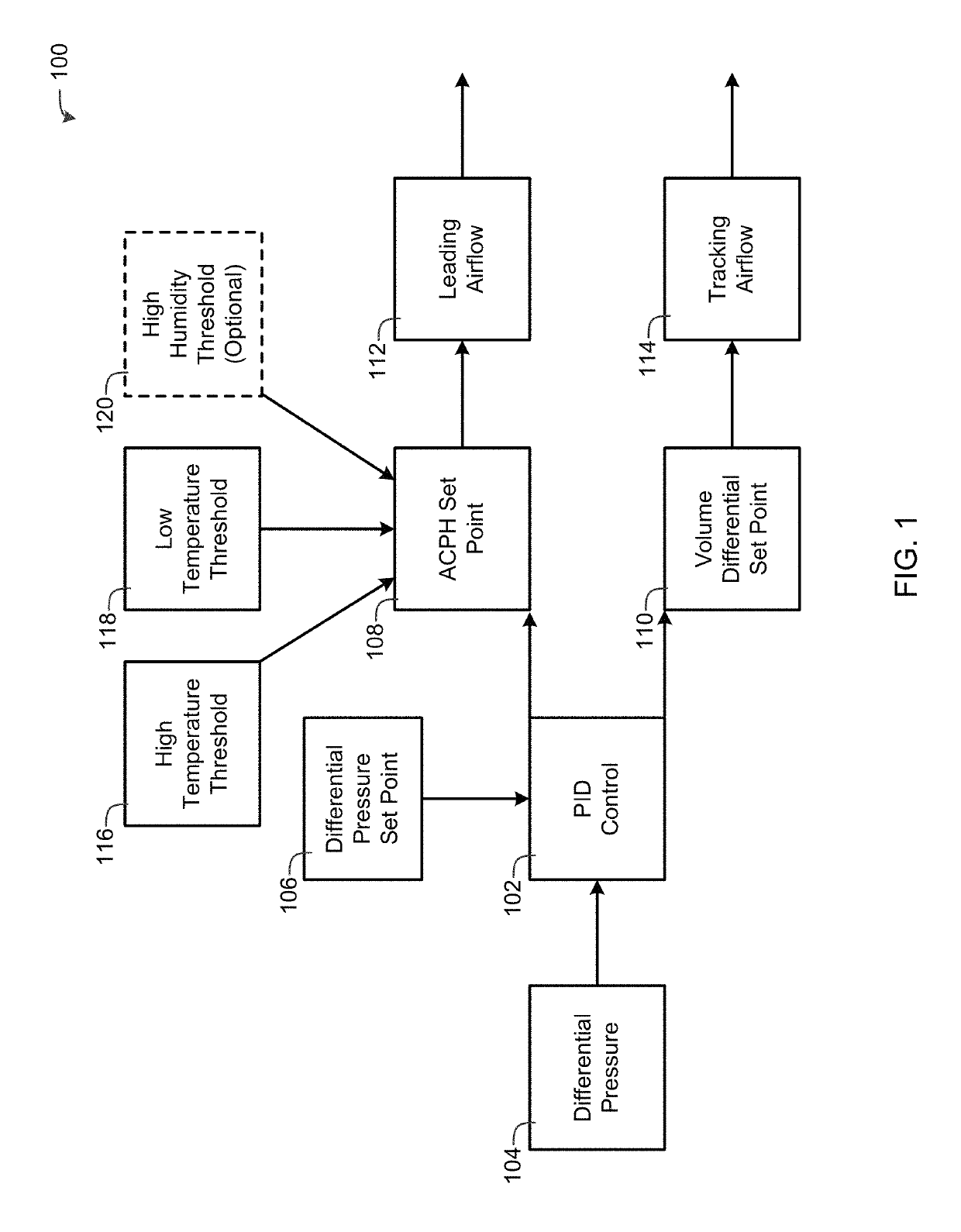
When static values, such as a differential pressure set point and air change per hour set point, are used for terminal box controller configuration, the room will typically have high energy usage, compliance related issues, or both when there is an event or unfavorable change in the heating, ventilating and air conditioning (HVAC) system.

Method used


Image

  • Adaptive optimization for dynamic room pressurization control
  • Adaptive optimization for dynamic room pressurization control
  • Adaptive optimization for dynamic room pressurization control

Examples


Embodiment Construction

[0018]The current invention now will be described more fully hereinafter with reference to the accompanying drawings, which illustrate embodiments of the invention. This invention may, however, be embodied in many different forms and should not be construed as limited to the illustrated embodiments set forth herein. Rather, these embodiments are provided so that this disclosure will be thorough and complete, and will fully convey the scope of the invention to those skilled in the art.

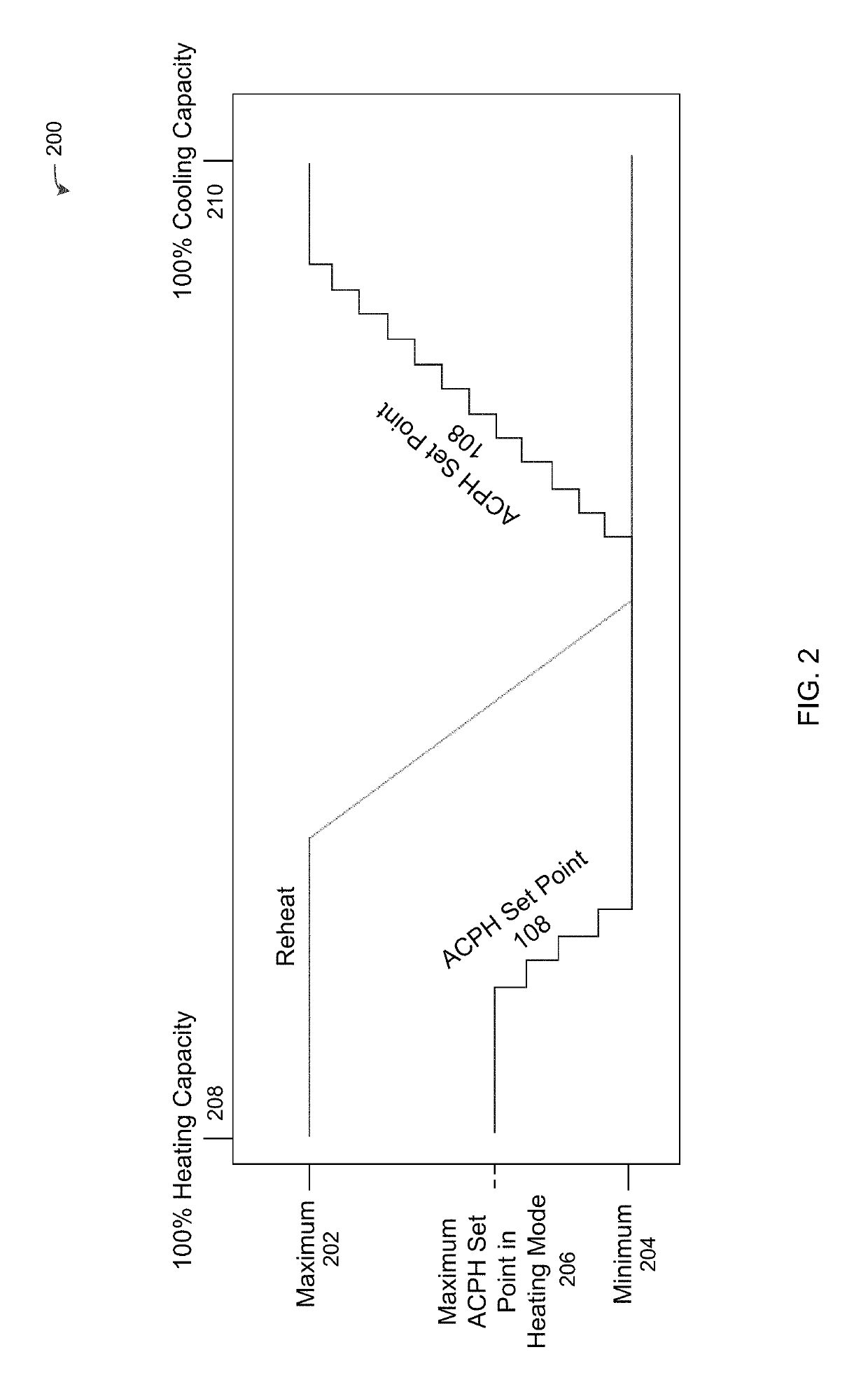
[0019]Adaptive Optimization for Dynamic Room Pressurization Control (AODRPC) is an innovative way to lower the outside air consumption of pressure dependent environments and adapt to adverse changes in the HVAC system automatically while maintaining space requirements. With AODRPC, the room will not only react accordingly to system malfunctions such as a pressure change in an adjacent space or the air distribution system, but will do it using the lowest possible air change rates for the application.

[002...


PUM

PropertyMeasurementUnit
humidityaaaaaaaaaa
humidityaaaaaaaaaa
differential pressureaaaaaaaaaa

Abstract

An apparatus and method controls an environmental control system to maintain a differential pressure between a room and one or more adjacent areas by (1) determining a differential pressure error based on the differential pressure and a differential pressure set point using a proportional-integral-derivative (PID) controller; (2) increasing an air change per hour set point whenever one or more first parameters are satisfied; (3) decreasing the air change per hour set point whenever one or more second parameters are satisfied; and (4) sending one or more control signals to the environmental control system that maintain the differential pressure between the room and the one or more adjacent areas by adjusting: (a) the leading airflow to be approximately equal to the air flow change set point multiplied by a volume of the room divided by 60, and (b) the tracking airflow to maintain a volume differential set point.

Description

CROSS-REFERENCE TO RELATED APPLICATIONS[0001]This non-provisional Patent Application claims priority to U.S. Provisional Patent Application Ser. No. 62 / 347,983, filed Jun. 9, 2016, entitled “Adaptive Optimization for Dynamic Room Pressurization Control,” the contents of which is incorporated by reference herein in its entirety.INCORPORATION-BY-REFERENCE OF MATERIALS FILED ON COMPACT DISC[0002]None.TECHNICAL FIELD OF THE INVENTION[0003]The present invention relates generally to the field of environmental control systems and, more particularly, to adaptively optimizing dynamic room pressurization control.STATEMENT OF FEDERALLY FUNDED RESEARCH[0004]None.BACKGROUND OF THE INVENTION[0005]Room pressurization is important for preventing unwanted airflow in certain environments, such as negative static pressure in chemical and biological facilities, or positive static pressure in food and drug processing operations. A room can be maintained at a negative static pressure with respect to an a...

Claims


Application Information

Patent Timeline
Patent Type & Authority Patents(United States)
IPC IPC(8): F24F11/64F24F11/00G01N1/26F24F11/30F24F11/65G05D16/00G05D16/20F24F110/50
CPCF24F11/0001F24F11/30F24F11/64G01N1/26G05D16/028G05D16/2073F24F11/65F24F2110/50Y02B30/70
Inventor ADKERSON, CURTIS D.
Owner BOARD OF RGT THE UNIV OF TEXAS SYST
Learn More