RF antenna producing a uniform near-field Poynting vector

a near-field poynting vector and antenna technology, applied in the direction of coatings, chemical vapor deposition coatings, electric discharge tubes, etc., can solve the problems of strong capacitance voltage, non-uniform semiconductor processing across the width of the substrate, and inability to produce plasma uniformly across the substra

Active Publication Date: 2019-07-16
LAM RES CORP
View PDF3 Cites 16 Cited by
  • Summary
  • Abstract
  • Description
  • Claims
  • Application Information

AI Technical Summary

Benefits of technology

[0006]The present embodiments relate to solving one or more problems found in the related art, and specifically to provide an radio frequency (RF) antenna generating a uniform near-field

Problems solved by technology

Plasma reaction and generation may not be uniform across the substrate.
As such, plasma generation is non-uniformly concentrated in a ring over the substrate, which results in non-uniform semiconductor

Method used


Image

  • RF antenna producing a uniform near-field Poynting vector
  • RF antenna producing a uniform near-field Poynting vector
  • RF antenna producing a uniform near-field Poynting vector

Examples


Embodiment Construction

[0037]Although the following detailed description contains many specific details for the purposes of illustration, anyone of ordinary skill in the art will appreciate that many variations and alterations to the following details are within the scope of the present disclosure. Accordingly, the aspects of the present disclosure described below are set forth without any loss of generality to, and without imposing limitations upon, the claims that follow this description.

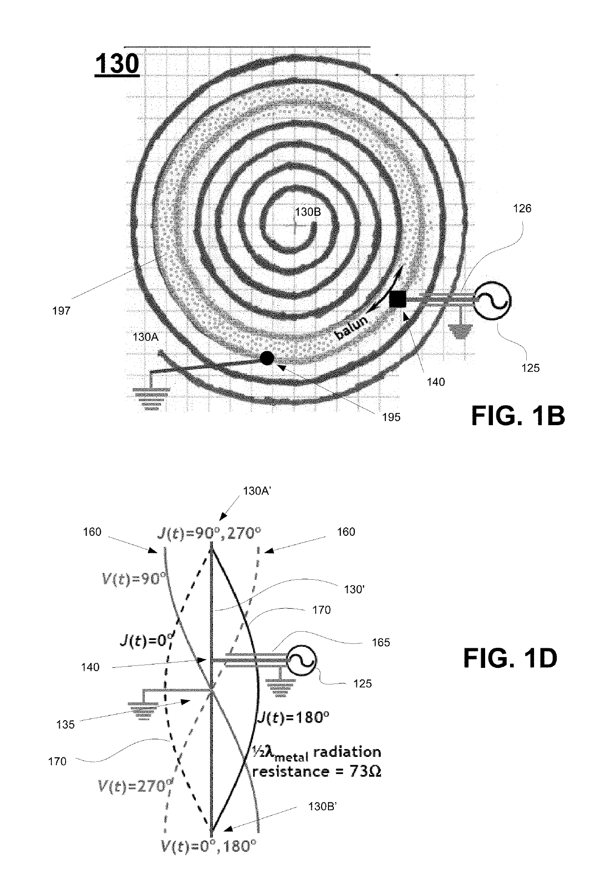
[0038]Generally speaking, the various embodiments of the present disclosure describe a class of quadrupole antennas that radiates not only from the high-current portion (e.g., center) of the antenna, but also from around the low-current portion of the antenna (e.g., the ends corresponding to the high voltage portions). The quadrupole antenna includes two 180 degree out-of-phase dipole antennas (and in one embodiment having equal-power) that takes advantage of the high-voltage tips having strong E (electric fields) that ...


PUM

PropertyMeasurementUnit
Angleaaaaaaaaaa
Lengthaaaaaaaaaa
Poweraaaaaaaaaa

Abstract

An apparatus for generating plasma, including a quadrupole antenna having a center region and an outer region and configured to be disposed over a dielectric window of a plasma chamber. The quadrupole antenna including a first coil defining a first SDA and a second coil defining a second SDA, the first coil being in a nested arrangement within the second coil. The nested arrangement places a turn of the first coil to be adjacent to a corresponding turn of the second coil as the first and second coils spiral from the center region to the outer region of the quadrupole antenna. Adjacent turns of each of the first and second coils are horizontally separated from one another by a distance when disposed over the dielectric window.

Description

TECHNICAL FIELD[0001]The present embodiments relate to semiconductor substrate processing equipment, and more particularly, a uniform near-field Poynting vector antenna generating a plasma in a chamber.BACKGROUND OF THE DISCLOSURE[0002]Plasma generation is performed in semiconductor processing systems including those performing deposition and etching, (e.g., plasma enhanced deposition and etching). Traditional plasma generating systems include transformer coupled plasma (TCP) systems, which is also referred to as inductively coupled plasma (ICP) systems. In TCP / ICP systems, the plasma contains various types of radicals, as well as positive and negative ions. The chemical reactions of the various radicals, positive ions, and negative ions are used, for example, to etch features, surfaces, and materials of the substrate. During the etching process, for example, a chamber coil performs a function analogous to that of a primary coil in a transformer, while the plasma performs a function...

Claims


Application Information

Patent Timeline
IPC IPC(8): H01J37/32H01L21/683H01L21/67C23C16/505
CPCH01J37/3211H01J37/32183H01L21/67069H01L21/6831C23C16/505H01J37/32119H01J2237/334H01J2237/332
Inventor MOPIDEVI, HEMA SWAROOPCHEN, LEEANDERSON, THOMAS W.
Owner LAM RES CORP
Why Eureka
Try Eureka