High intensity focused ultrasound positioning mechanism

a positioning mechanism and high intensity technology, applied in the field of positioning mechanisms, can solve the problems of increasing the cost of the combined magnetic resonance imaging and high intensity focused ultrasound unit, and the space available for the mechanism is extremely limited, so as to reduce the amount of metal used

Active Publication Date: 2019-07-23
PROFOUND MEDICAL
View PDF21 Cites 0 Cited by
  • Summary
  • Abstract
  • Description
  • Claims
  • Application Information

AI Technical Summary

Benefits of technology

[0008]A rod as used herein is understood to be a rigid body. A rod functions or is equivalent to a link in a linkage or mechanical linkage. The mechanism further comprises a plurality of linear drives. The plurality of linear drives is mounted to the mechanism support. Each of the linear drives comprises a drive block. The second end of each of the plurality of rods forms a separate ball joint with one of the drive blocks. A mechanism which embodies this has several advantages. A very compact mechanism can be constructed. The number of sliding parts can also be reduced. In addition an embodiment of such a mechanism allows the calculation of how the mechanism may be positioned to put the positioning plate in a particular position or place. This allows precise control and positioning of a high intensity focused ultrasound transducer.
[0026]The control system could also be more sophisticated, it could include a processor which is capable of performing the calculations necessary to actuate the mechanism along a predetermined path between a first point and a second point. In this case the control system may be a processor which is capable of modeling the motion of the mechanism. An embodiment of this invention of this high intensity focused ultrasound unit is advantageous, because the mechanism may use a reduced amount of space. This provides for a more compact high intensity focused ultrasound unit.

Problems solved by technology

For instance all the parts may be non magnetic materials and may be able to tolerate the ultrasound conducting medium which the high intensity focused ultrasound transducer is immersed in, the construction of the mechanism is placed into a watertight container so the mechanism may also be watertight, the space available for the mechanism is extremely limited, because the bore or the region of the magnet for magnetic resonance imaging needs to accommodate both the patient, the mechanism and the high intensity focused ultrasound unit.
Using a larger mechanism requires the use of a magnet with a larger bore and therefore increases the cost of the combined magnetic resonance imaging and high intensity focused ultrasound unit.

Method used


Image

  • High intensity focused ultrasound positioning mechanism
  • High intensity focused ultrasound positioning mechanism
  • High intensity focused ultrasound positioning mechanism

Examples


Embodiment Construction

[0045]Like numbered elements in these figures are either equivalent elements or perform the same function. Elements which have been discussed previously will not necessarily be discussed in later figures if the function is equivalent.

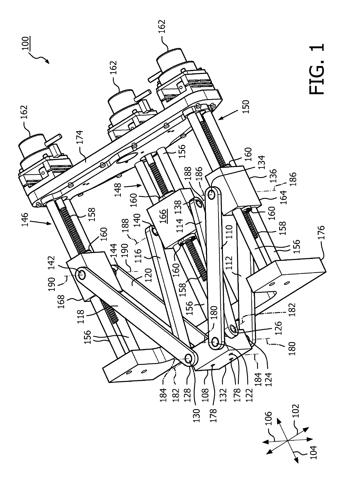
[0046]FIG. 1 shows a mechanism 100 according to an embodiment of the invention. This mechanism has three linear drives 146, 148, 150. The mechanism 100 is adapted for moving the positioning plate 108 along three orthogonal axes, the x axis 102, the y axis 104, and the z axis 106. The choice of x, y and z for labeling the axes is an arbitrary choice. In FIG. 1 a first rod 110, a second rod 112, a third rod 114, a fourth rod 116, a fifth rod 118, and a sixth rod 120 are shown. The first rod 110 forms a first ball joint 122 with the positioning plate 108. The second rod 112 forms a second ball joint 124 with the positioning plate 108. The third rod 114 forms a third ball joint 126 with the positioning plate 108. The fourth rod 116 forms a fourth ball joint...


PUM


Abstract

A high intensity focused ultrasound positioning mechanism (100, 200, 310) for positioning a high intensity focused ultrasound transducer (292, 304), the mechanism comprising: —a positioning plate (108, 308) adapted for receiving the high intensity focused ultrasound transducer; —a mechanism support (174) adapted for mounting the positioning mechanism; —a plurality of rods (110, 112, 114, 116, 118, 120, 210, 212, 214, 216, 218, 220), wherein each rod has a first end and an second end, wherein the first end of each rod forms a separate ball joint (122, 124, 126, 128, 130, 132, 222, 224, 226, 228, 230, 232) with the positioning plate; and —a plurality of linear drives (146, 148, 150, 246, 248, 250, 252, 254), wherein the plurality of linear drives are mounted to the mechanism support, wherein each of the linear drives comprises a drive block (164, 166, 168, 264, 266, 268, 270, 272), wherein the second end of each of the plurality of rods forms a separate ball joint (134, 136, 138, 140, 142, 144, 234, 236, 238, 240, 242, 244) with one of the drive blocks.

Description

TECHNICAL FIELD[0001]The invention relates to a positioning mechanism, in particular a positioning mechanism for positioning a high intensity focused ultrasound transducer in a high intensity focused ultrasound system.BACKGROUND OF THE INVENTION[0002]In high intensity focused ultrasound, focused ultrasound is used for sonicating or treating a region of tissue within a subject with high intensity focused ultrasound. The high intensity focused ultrasound can be used for heating a region within the subject, it can be used for rupturing tiny capsules of a drug and activating the drug, it can be used for ablating tissue, and at higher powers cavitation can be used to destroy regions within the subject. High intensity focused ultrasound is focused onto a region of the subject using a transducer. Very often the transducers have multiple elements and by controlling the phase and amplitude of the individual elements the focus of the ultrasound within the subject can be adjusted to a certain ...

Claims


Application Information

Patent Timeline
Patent Type & Authority Patents(United States)
IPC IPC(8): A61B5/05A61N7/02A61N7/00A61B90/00
CPCA61N7/02A61N2007/0091A61B2090/374
Inventor SALMINEN, HEIKKI
Owner PROFOUND MEDICAL
Why Eureka
Try Eureka