Optical fiber connector ferrule having curved external alignment surface

a technology ferrules, which is applied in the field of optical fiber connectors, can solve the problems of increasing connector insertion loss and reflection loss, increasing the loss of connectors, and inherently not holding tolerance well, and achieving the effects of high temperature stability, low thermal expansion, and high stiffness

Active Publication Date: 2019-07-23
SENKO ADVANCED COMPONENTS
View PDF35 Cites 2 Cited by
  • Summary
  • Abstract
  • Description
  • Claims
  • Application Information

AI Technical Summary

Benefits of technology

[0026]The present invention provides a ferrule for an optical fiber connector, which overcomes many of the drawbacks of the prior art ferrules and connectors, and further improves on applicant's pin-less alignment ferrules. The ferrule in accordance with the present invention provides an optical fiber connector having an optical fiber ferrule, which results in low insertion loss and low return loss, which provides ease of use and high reliability with low environmental sensitivity, and which can be fabricated at low cost. Given the configuration of the inventive ferrules, the foot-print or form factor of the housing of the optical fiber connector using the inventive ferrule for multi-fibers can be similar to that of housings that currently use prior art cylindrical ferrules designed for only a single fiber (i.e., the inventive ferrules may be incorporated in industry standard connector housings designed for single fiber, such as SC, FC, ST, SMA, LC, Dual LC, etc., type housings.)
[0032]In one embodiment, the ferrule body is made of a metal material, which may be chosen to have high stiffness (e.g., stainless steel), chemical inertness (e.g., titanium), high temperature stability (nickel alloy), low thermal expansion (e.g., Invar), or to match thermal expansion to other materials (e.g., Kovar for matching glass).
[0033]The ferrule in accordance with the present invention overcomes many of the deficiencies of the prior art, resulting in an optical fiber connector that results in low insertion loss and low return loss, which provides ease of use and high reliability with low environmental sensitivity, and which can be fabricated at low cost.

Problems solved by technology

These devices couple fibers in an end-to-end relationship, with the coupling being one source of light loss.
Physical contact avoids a trapped layer of air between two fibers, which increases connector insertion loss and reflection loss.
The injection molded structure inherently does not hold tolerance well.
Polymers are also susceptible to creep and thermal expansion / contraction over longer periods of time.
The epoxy shrinks upon curing, which leads to bending of the plastic ferrule.
Further, epoxy creeps over time, leading to pistoning or retracting of the optical fiber ends (which are pushed against the ends of adjoining fibers) within the holes in the ferrule under the applied axial bias of the spring-load in the connector.
This compromises the integrity of the surface contact interface of opposing fiber end faces.
These and other deficiencies result in poor resultant tolerance that is more to be desired for modern day optical fiber applications.
Currently, it is generally accepted that current fiber connectors cost too much to manufacture and the reliability and loss characteristics are more to be desired.

Method used


Image

  • Optical fiber connector ferrule having curved external alignment surface
  • Optical fiber connector ferrule having curved external alignment surface
  • Optical fiber connector ferrule having curved external alignment surface

Examples


Embodiment Construction

[0034]This invention is described below in reference to various embodiments with reference to the figures. While this invention is described in terms of the best mode for achieving this invention's objectives, it will be appreciated by those skilled in the art that variations may be accomplished in view of these teachings without deviating from the spirit or scope of the invention.

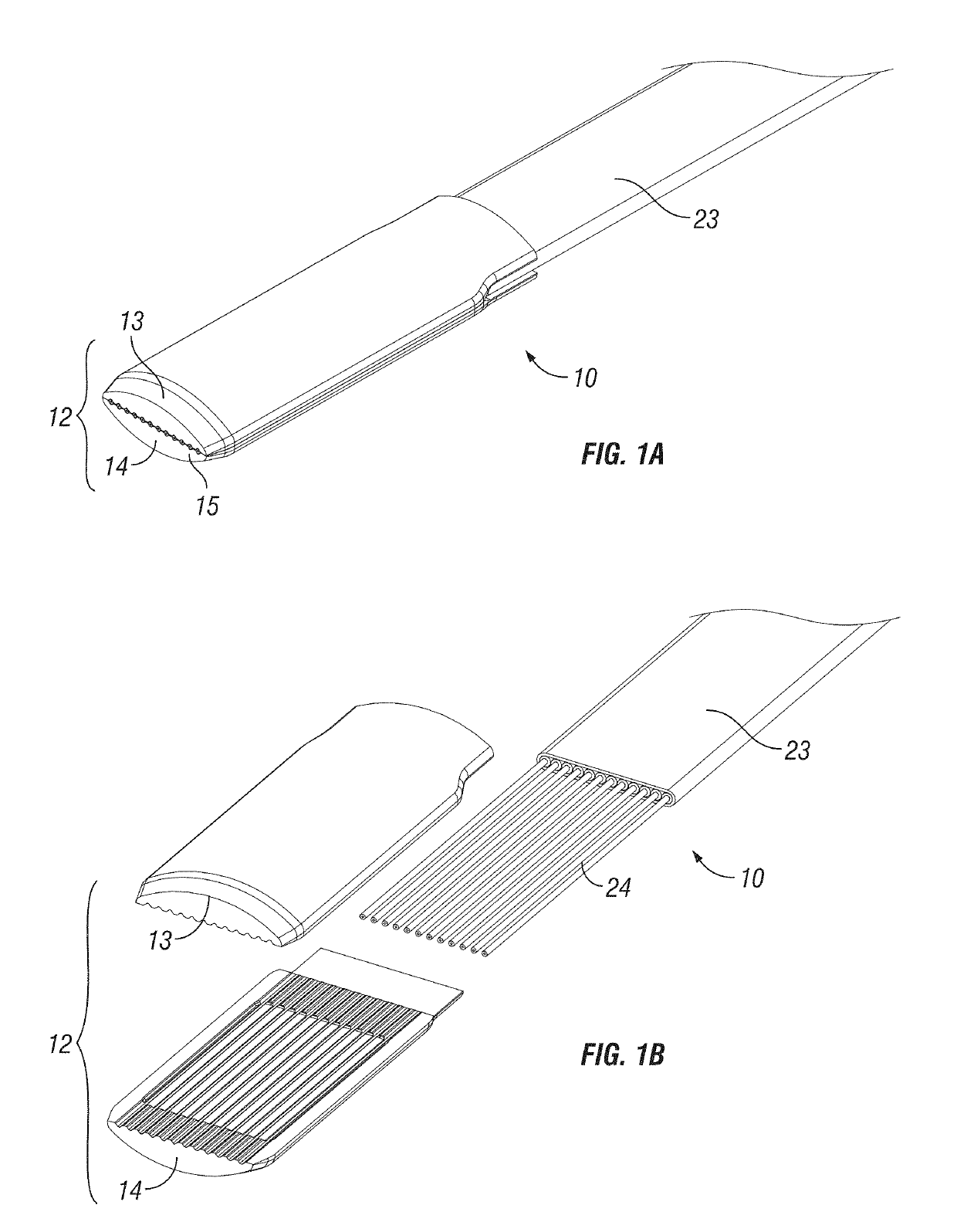
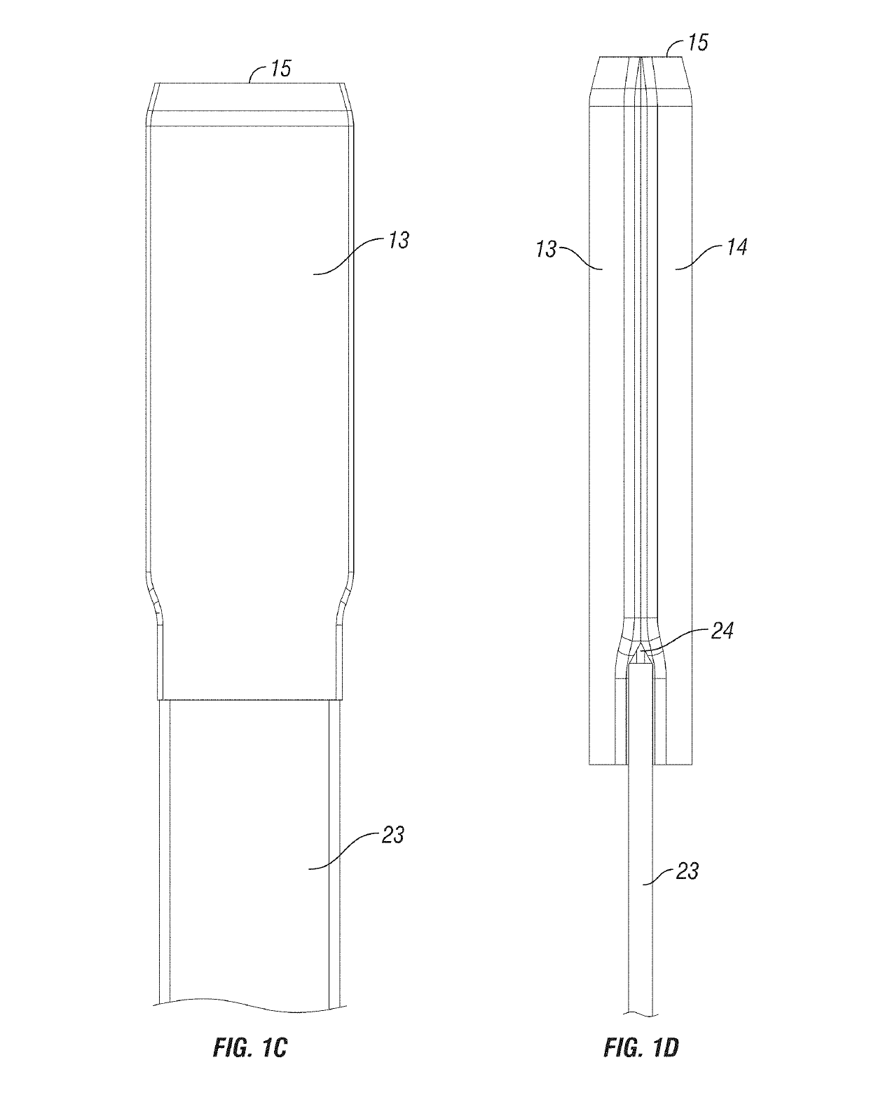
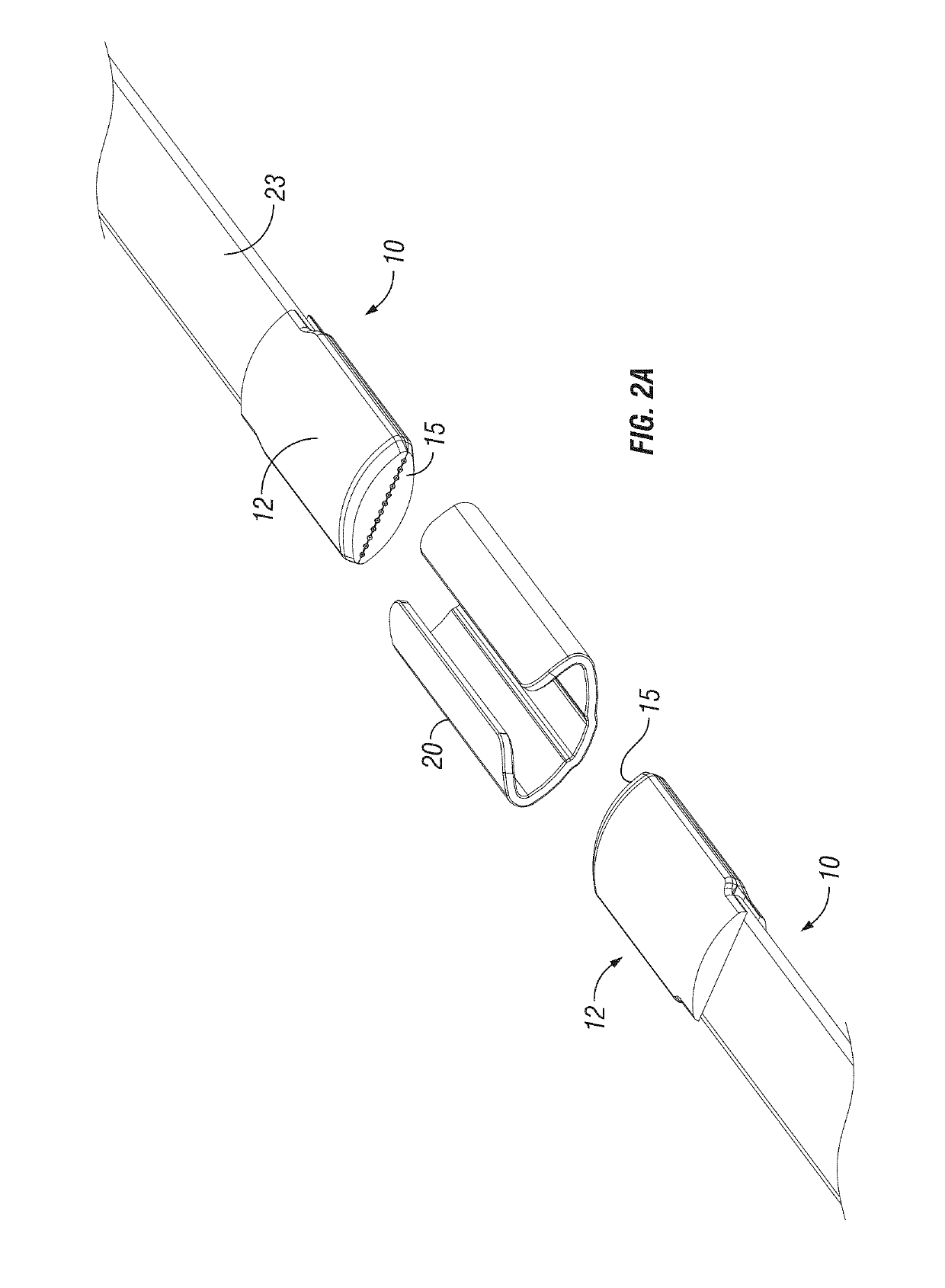
[0035]The present invention provides a ferrule for an optical fiber connector, which overcomes many of the drawbacks of the prior art ferrules and connectors, and further improves on applicant's pin-less alignment ferrules. The ferrule in accordance with the present invention provides an optical fiber connector having an optical fiber ferrule, which results in low insertion loss and low return loss, which provides ease of use and high reliability with low environmental sensitivity, and which can be fabricated at low cost. Given the configuration of the inventive ferrules, the foot-print or form factor of t...


PUM


Abstract

A ferrule for an optical fiber connector has an external surface for alignment with a complementary surface of an alignment sleeve (i.e., the inside surface of a generally cylindrical or tubular sleeve). The external surface of the ferrule is generally cylindrical, having a sectional contact surface profile that is generally oval in shape. More specifically, a plurality of points of contact between the ferrule and the sleeve are defined along a curve in cross-section, wherein the center of curvature at each of the contact points along this contact point curve (i.e., the curve containing contact points that contribute to alignment) does not lie in the plane of the axis of the array of optical fibers.

Description

PRIORITY CLAIM[0001]This application claims the priority of U.S. Provisional Patent Application No. 61 / 623,029 filed on Apr. 11, 2012, and U.S. Provisional Patent Application No. 61 / 699,125 filed on Sep. 10, 2012, which are fully incorporated by reference as if fully set forth herein. All publications noted below are fully incorporated by reference as if fully set forth herein.GOVERNMENT RIGHTS[0002]This invention was made with government support under Contract No. N68335-12-C-0123 awarded by NAVAL AIR WARFARE CTR AIRCRAFT DIVISION. The government has certain rights in the invention.BACKGROUND OF THE INVENTIONField of the Invention[0003]The present invention relates to optical fiber connectors, in particular ferrules in optical fiber connectors.Description of Related Art[0004]There are many advantages of transmitting light signal via optical fiber waveguides and the use thereof is diverse. Single or multiple fiber waveguides may be used simply for transmitting visible light to a rem...

Claims


Application Information

Patent Timeline
Patent Type & Authority Patents(United States)
IPC IPC(8): G02B6/38
CPCG02B6/3822G02B6/3855G02B6/3825G02B6/389G02B6/3636G02B6/3839G02B6/3861G02B6/4214G02B6/4248G02B6/3874G02B6/3877G02B6/3885G02B6/42
Inventor LI, SHUHEVALLANCE, ROBERT RYANBARNOSKI, MICHAEL K.
Owner SENKO ADVANCED COMPONENTS
Why Eureka
Try Eureka