Foldable display device and method for manufacturing the same

a display device and folding technology, applied in the field of display devices, can solve the problems of increasing the processing time and cost, the boundary (or steps) between the non-adhesive area and the adhesive area, and the inability to so as to reduce the visibility of the step, remove the step difference, and reduce the effect of adhesive strength

Active Publication Date: 2019-07-23
SAMSUNG DISPLAY CO LTD
View PDF16 Cites 7 Cited by
  • Summary
  • Abstract
  • Description
  • Claims
  • Application Information

AI Technical Summary

Benefits of technology

[0029]Therefore, the foldable display device according to example embodiments may include the coating layer disposed on the non-adhesive area of the support member corresponding to the folding area to weaken an adhesive strength and to remove (or improve) a step difference, and the adhesive member may be integrally formed on the support member. Thus, the step (or the step difference) between the folding area (e.g., the non-adhesive area) and its adjacent area (e.g., the adhesive area) may be eliminated, and the poor visibility in which the step is visible may be reduced.
[0030]In addition, the method for manufacturing the foldable display device may simplify the bonding (or attaching) process by forming the thin coating layer that weakens the adhesive strength in the non-bonding area corresponding to the folding area and integrally forming the adhesive member on the support member. Further, the step between the adhesive area and the non-adhesive area can be eliminated by the thin coating layer and the integrally formed adhesive member. Therefore, the manufacturing cost can be reduced and the process time can be shortened. In addition, boundaries (or steps) between the non-adhesive area and the adhesive area may not be visually recognized, thereby improving visibility.

Problems solved by technology

However, since a curvature of the foldable display panel that naturally bends or folds is different from a curvature of a folded portion (e.g., a hinge portion) of the support member, the foldable display panel and the support member separate (peel off) at this portion.
In addition, a process and a member for compensating the step are added so that the processing time and cost increase.
In addition, boundaries (or steps) between the non-adhesive area and the adhesive area may not be visually recognized, thereby improving visibility.

Method used


Image

  • Foldable display device and method for manufacturing the same
  • Foldable display device and method for manufacturing the same
  • Foldable display device and method for manufacturing the same

Examples


Embodiment Construction

[0038]Exemplary embodiments will be described more fully hereinafter with reference to the accompanying drawings, in which various embodiments are shown.

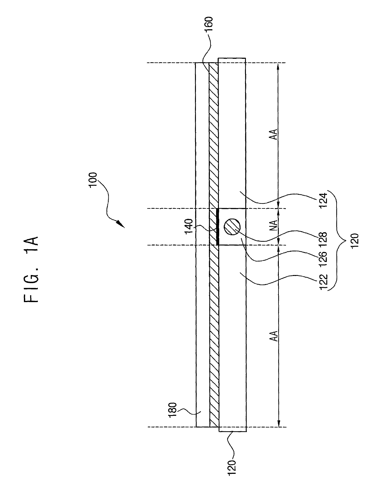
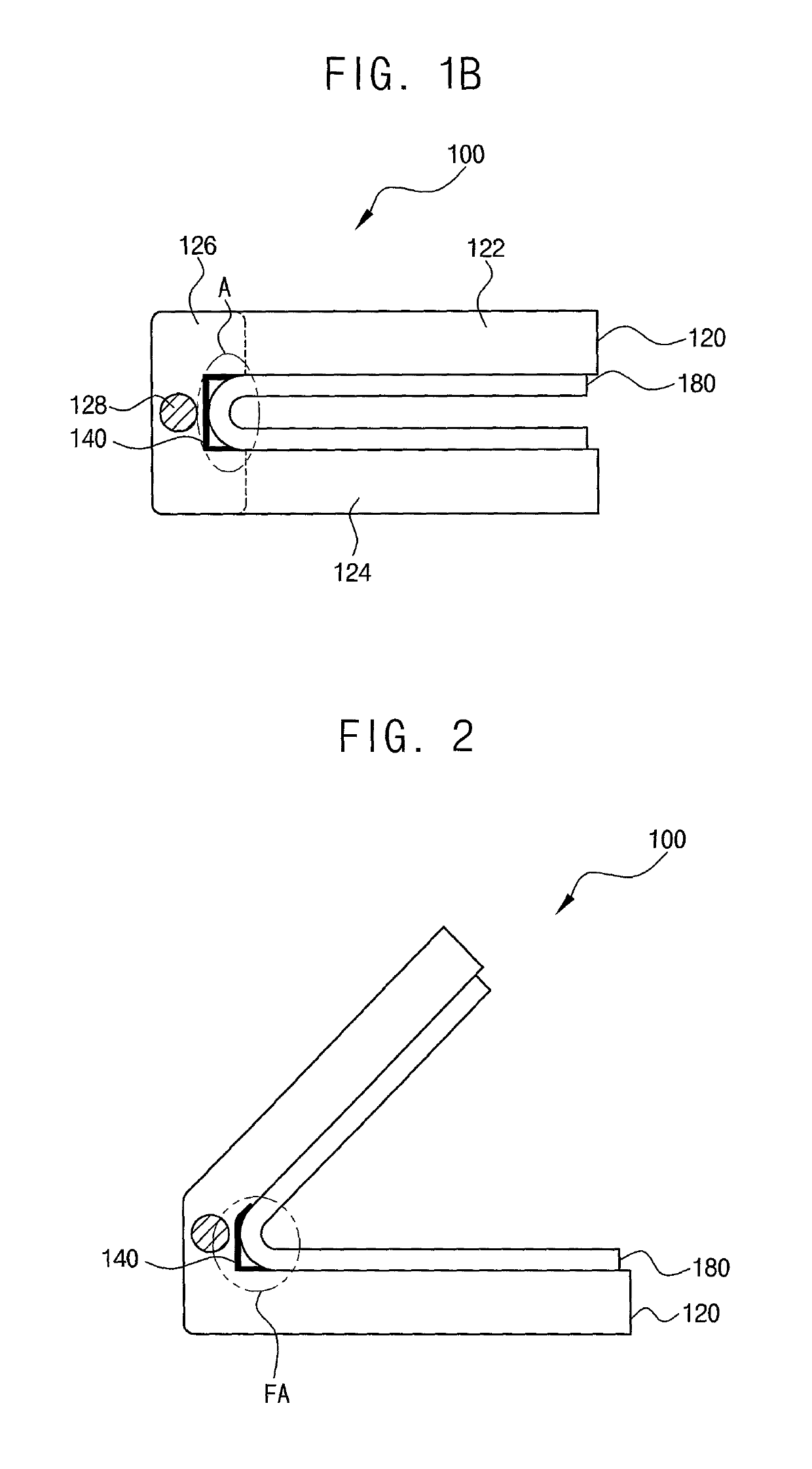
[0039]FIGS. 1A and 1B are cross-sectional views schematically illustrating a foldable display device according to example embodiments.

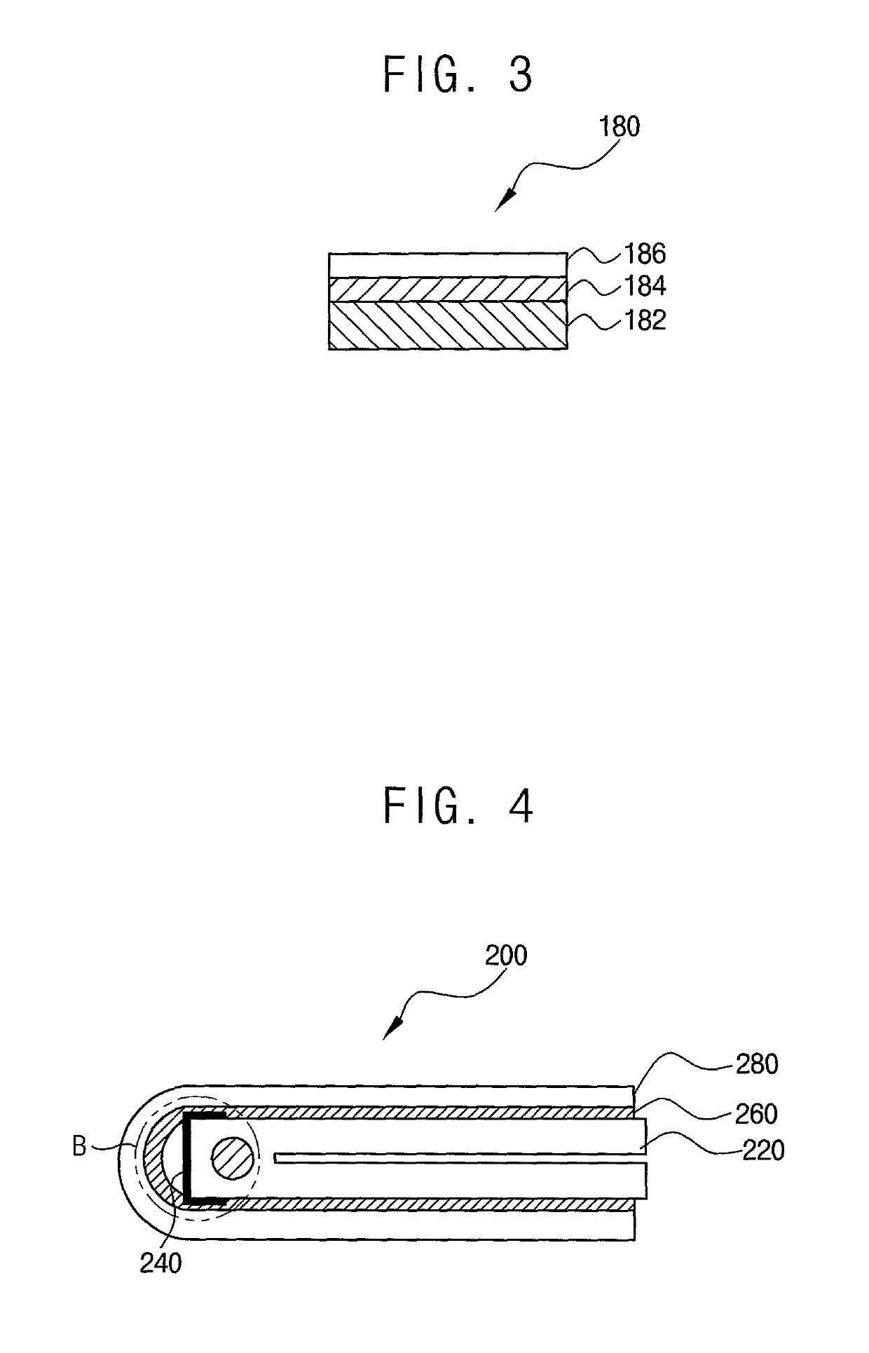
[0040]Referring to FIGS. 1A and 1B, the foldable display device 100 may include a support member 120, a coating layer 140, an adhesive member 160, and a foldable display module 180.

[0041]FIG. 1A shows a cross-sectional view of the foldable display device 100 in a fully unfolded state, and FIG. 1B shows a cross-sectional view of the foldable display device 100 in a fully folded state.

[0042]The support member 120 may include a first support portion 122, a second support portion 124, and a hinge portion 126. In some embodiments, the support member 120 may be formed of a metal and / or a plastic material, and may have a housing structure. However, the material and structure of the support member 120 are not...


PUM

PropertyMeasurementUnit
thicknessaaaaaaaaaa
thicknessaaaaaaaaaa
thicknessaaaaaaaaaa

Abstract

A foldable display device according to example embodiments includes a support member including a first support portion, a second support portion, and a hinge portion connected between the first support portion and the second support portion, the support member being divided into an adhesive area and a non-adhesive area, a coating layer on the non-adhesive area of the support member, an adhesive member integrally on the adhesive area of the support member and the coating layer, and a foldable display module attached on the adhesive member.

Description

CROSS REFERENCE TO RELATED APPLICATION[0001]This application claims priority to and the benefit of Korean Patent Application No. 10-2017-0046134, filed on Apr. 10, 2017, in the Korean Intellectual Property Office (KIPO), the entire content of which is hereby incorporated by reference.BACKGROUND1. Field[0002]Example embodiments of the inventive concept relate to display devices. More particularly, example embodiments of the inventive concept relate to foldable display devices including a foldable display module.2. Discussion of Related Art[0003]A foldable display device, a bendable display device, rollable display, or the like utilizing the advantages of a flexible display panel that can be bent or folded has been recently developed. Such a display device can be applied to various fields such as a television, a monitor, and the like as well as a portable electronic device and a wearable device.[0004]In the case of a foldable display device, a foldable display panel and a support memb...

Claims


Application Information

Patent Timeline
Patent Type & Authority Patents(United States)
IPC IPC(8): G06F1/16H05K5/00H05K5/02E05D3/02G09F9/30B32B37/12
CPCH05K5/0226G06F1/1641G06F1/1652G06F1/1681H05K5/0017G09F9/301B32B37/12B32B2457/20E05D3/02E05Y2900/606Y02E10/549Y02P70/50G02F1/133305H10K59/00H10K77/111
Inventor AHN, SUNGSANG
Owner SAMSUNG DISPLAY CO LTD
Why Eureka
Try Eureka