Particle beam therapy apparatus

a particle beam therapy and apparatus technology, applied in the field can solve the problems of prolonged treatment time and complicated mechanisms of particle beam therapy apparatus, and achieve the effects of shortening treatment time, simple structure, and high quality x-ray

Active Publication Date: 2019-07-30
KK TOSHIBA +1
View PDF11 Cites 2 Cited by
  • Summary
  • Abstract
  • Description
  • Claims
  • Application Information

AI Technical Summary

Benefits of technology

[0014]An object of the present invention is to provide a particle beam therapy apparatus that can acquire a high-quality X-ray image with a simple structure and shorten treatment time.Means for Solving Problem

Problems solved by technology

However, the above-described technique has a problem that the arms and their control mechanisms complicate the particle beam therapy apparatus and the treatment time is prolonged by the arrangement time and retraction time of the X-ray imaging devices.

Method used


Image

  • Particle beam therapy apparatus
  • Particle beam therapy apparatus
  • Particle beam therapy apparatus

Examples


first embodiment

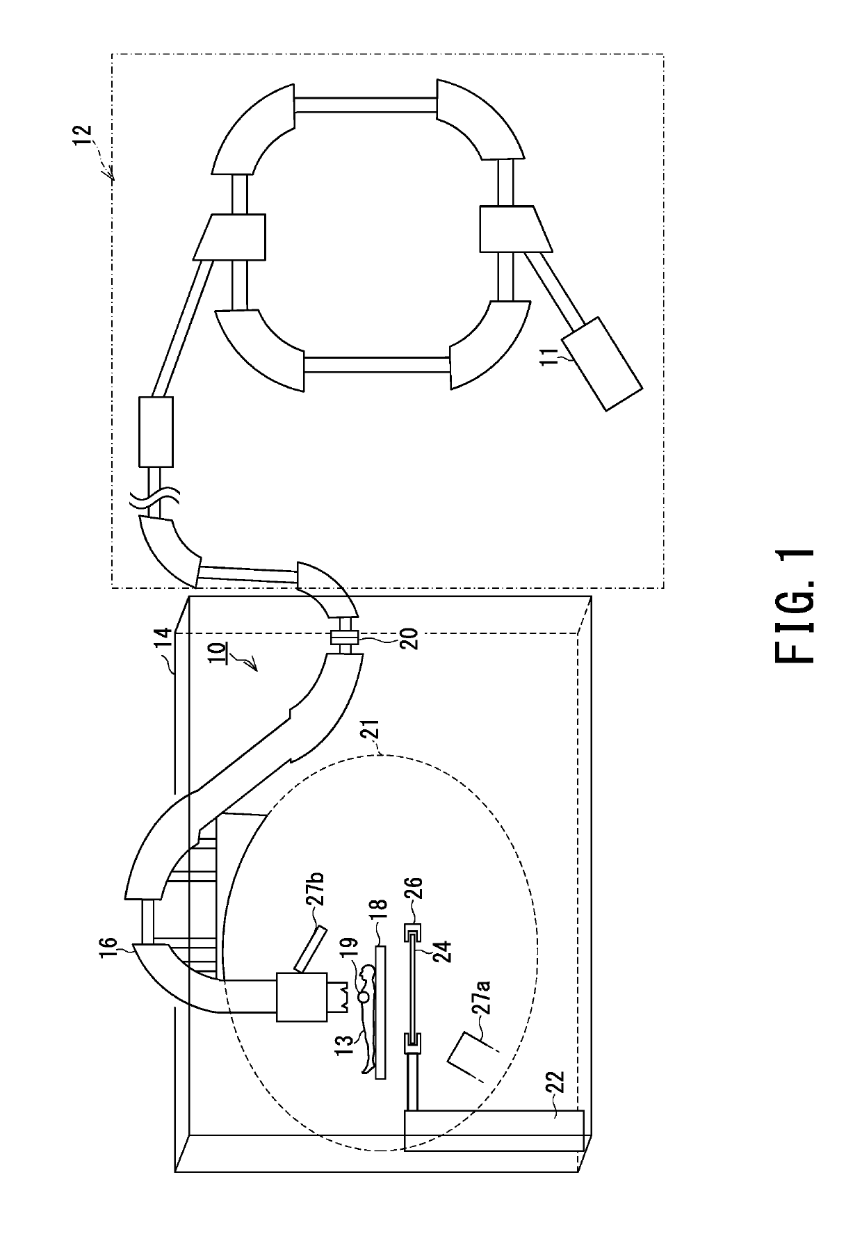
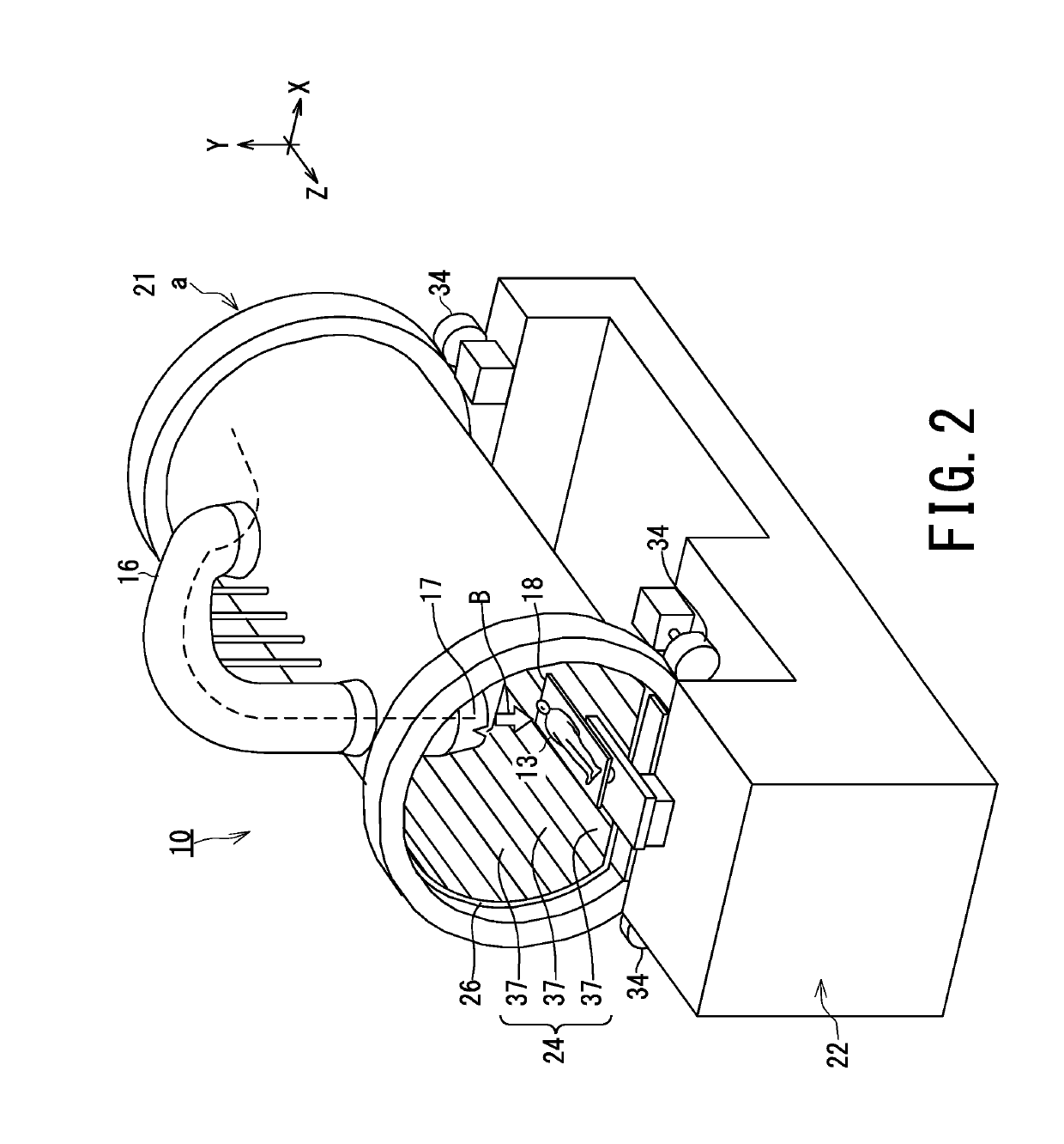
[0053]FIG. 2 is a diagram illustrating the treatment apparatus 10 according to the first embodiment equipped with a rotating gantry 21a of full rotation type.

[0054]Since the particle beam irradiator 16 is provided with a large number of structures (not shown) such as a vacuum duct, a beam deflection electromagnet, an irradiation field forming electromagnet, various monitors, and a gantry, the particle beam irradiator 16 is considerably heavy.

[0055]Thus, in many cases, a cylindrical rotating gantry 21a (21) of full rotation type as shown in FIG. 2 is used in order to stably support and displace the heavy particle beam irradiator 16.

[0056]Such a rotating gantry 21a is placed on, e.g., rotation drivers 34 that are installed on the base 22, and rotates around the central axis (i.e., Z axis) of the cylinder by the rotation of the rotation driver 34.

[0057]The particle beam irradiator 16 is fixed in such a manner that the tip portion of the particle beam irradiator 16 protrudes toward trea...

second embodiment

[0127](Rotating Gantry 21b of Partial Rotation Type)

[0128]FIG. 7 is a schematic configuration diagram of the treatment apparatus 10 according to the second embodiment.

[0129]In recent years, as shown in FIG. 7, there is known a rotating gantry 21b (21) of partial rotation type with the use of, for example, rail tracks 40 or a part of a cylinder.

[0130]In FIG. 7, various accompanying devices such as balance weights that are connected to the particle beam irradiator 16 and balance the weight with the particle beam irradiator 16 are omitted.

[0131]In the rotating gantry 21b shown in FIG. 7, two rail tracks 40 in a curved shape and in an angle range smaller than 360 degrees are provided.

[0132]Two rotation auxiliary bodies 25 are engaged with these two rail tracks 40.

[0133]The particle beam irradiator 16 is supported by the rotation auxiliary bodies 25 and rotates at an angle smaller than 360 degrees around the patient 13 fixed to the table 18.

[0134]In the case of using the rotating gantry ...

third embodiment

[0152](Correction of Relative Peripheral Angle of First Floor Member 37a and Particle Beam Irradiator 16)

[0153]FIG. 9A and FIG. 9B are schematic cross-sectional views illustrating the treatment apparatus 10 according to the third embodiment.

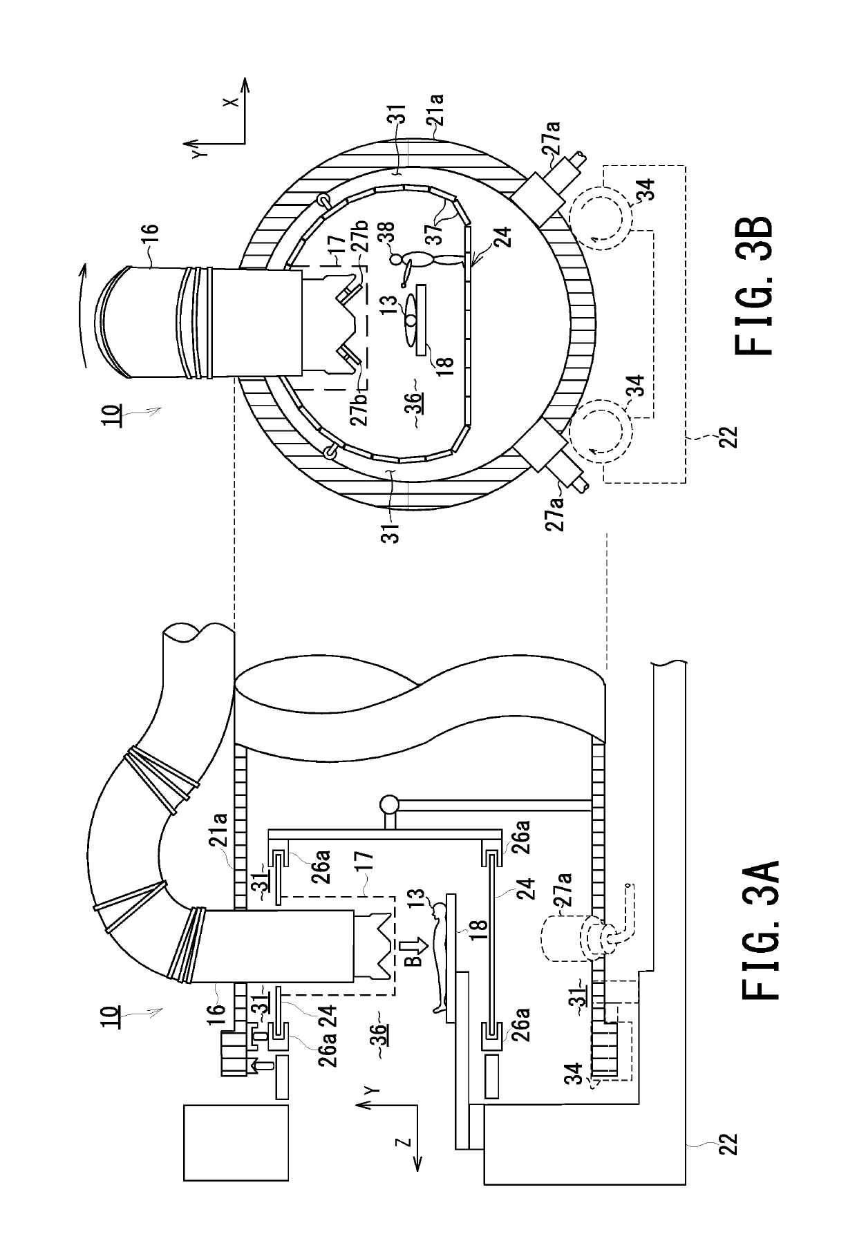
[0154]FIG. 9A is a cross-sectional view of the treatment apparatus 10 equipped with the rotating gantry 21a of full rotation type shown in FIG. 2, taken along the central axis of the rotating gantry 21a in a manner similar to FIG. 3A.

[0155]In addition, FIG. 9B is a cross-sectional view of the treatment apparatus 10 in the direction perpendicular to the central axis, similarly to FIG. 3B.

[0156]As shown in FIG. 9A and FIG. 9B, in addition to the configuration of the first embodiment, the treatment apparatus 10 according to the third embodiment further includes a sensor 44 for detecting the position of the first floor member 37a and a position adjuster 46 that slides the movable plates 37 on the basis of the position of the first floor member 37a so...


PUM


Abstract

A particle beam therapy apparatus includes: a particle beam irradiator outputting a particle beam; a movable supporting structure supporting the particle beam irradiator; movable plates disposed on a displacement trajectory of the particle beam irradiator, forming a substantially horizontal enveloping surface below a table for placing an irradiation object, and including first and second floor members in at least one of the movable plates, the second floor member being larger in X-ray transmittance than the first floor member; an X-ray generator provided in a non-collision area where the X-ray generator does not collide with any of the particle beam irradiator, the supporting structure, and the movable plates; and an X-ray detector installed at a position where the X-ray detector faces the X-ray generator.

Description

FIELD[0001]Embodiments of the present invention relate to a particle beam therapy apparatus (i.e., particle beam therapy device) equipped with a rotating gantry.BACKGROUND[0002]In cancer treatment in recent years, a particle beam therapy method is widely used. In the particle beam therapy method, a cancer lesion area is irradiated with a particle beam that is generated by accelerating charged particles such as protons and carbon ions to high energy.[0003]In the particle beam therapy method, in order to irradiate a cancer lesion area with a particle beam without irradiating important organs, it is required to perform irradiation changing the irradiation angle of the beam variously. Thus, for instance, a particle beam irradiator is fixed to a cylindrical rotating gantry to rotate together, thereby is changed its irradiation angle.[0004]The inner space of the rotating gantry serving as a treatment room is provided with a movable floor that maintains a flat horizontal floor surface rega...

Claims


Application Information

Patent Timeline
Patent Type & Authority Patents(United States)
IPC IPC(8): A61N5/10A61B6/00
CPCA61N5/1049A61B6/4007A61B6/4266A61N5/10A61N5/1078A61B6/4452A61N2005/1087A61N2005/1061A61B6/102A61B6/50A61B6/12A61N5/1081A61B6/0442A61B6/587A61B6/4014A61B6/4435A61N5/1065A61N5/1071A61B6/022A61B6/107A61B6/4233A61B6/4476A61B6/0487
Inventor NAGAMOTO, YOSHIFUMIKITAGAWA, KIYOHIKOMAETA, KAZUTAKA
Owner KK TOSHIBA
Why Eureka
Try Eureka