Wind turbine for use in high winds

a wind turbine and high-wind technology, applied in the direction of machines/engines, sustainable buildings, mechanical equipment, etc., can solve the problems of finite fossil fuel supply, uncompetitive cost of this power, and other drawbacks of fossil fuel combustion

Active Publication Date: 2019-07-30
WILLIAMS DARELL ALLEN
View PDF25 Cites 1 Cited by
  • Summary
  • Abstract
  • Description
  • Claims
  • Application Information

AI Technical Summary

Benefits of technology

[0006]Bech describes a wind-powered turbine with an improved drive train in U.S. Pat. No. 8,403,786. This turbine includes improvements over turbines of the previous design, but Bech's turbine does not include many of the improved features of the present invention, such as the ability to support the turbine from above, and the ability to move the windmill connected to the turbine to catch the greatest amount of wind, and the “shroud” which increases the amount of wind energy which is funneled through the windmill so that it eventually reaches the turbine.
[0007]Bech describes another wind-powered turbine with an improved drive train in U.S. Pat. No. 8,585,367. The main bearing unit of this turbine has multiple rings. However, this invention does not include the ability to support the turbine from above, and the ability to move the windmill connected to the turbine to catch the greatest amount of wind, and the “shroud” which increases the amount of wind energy which is funneled through windmill and eventually reaches the turbine.
[0009]In U.S. Pat. No. 8,338,979, Bray et. al. describe another generator with superconducting components, which can be attached to a wind-powered turbine. This has certain improvements over the Laskaris patent, and they also claim the generator, and certain associated methods, as their invention. Bray describes an electricity-generating windmill which lacks many of the improved features of the present invention, such as the ability to support the turbine from above, and the ability to move the blades to catch the greatest amount of wind, and the “shroud” which increases the amount of wind energy which is funneled through the turbine.
[0011]Todoroff also does not include the shroud, which maximizes the amount of wind energy flowing through the rotor. The wind turbine of the present invention is also adjustable for height, which is a feature lacking in Todoroff.
[0013]Russ et. al. describe a bearing unit for rotor blades, which can be used to absorb the force that wind pressure may exert upon the rotor and blades of a windmill. However, Russ' invention speaks to a bearing unit, not to a windmill that generates electricity, and therefore lacks many of the improved features of the present invention, such as the ability to support the rotor from above, and the ability to move the sections of the blades to catch the greatest amount of wind, and the “shroud” which increases the amount of wind energy which is funneled through the turbine.
[0014]Apthorp discloses, in U.S. Pat. No. 8,148,841, a modular windmill system with stacked groups of blades. The stacked configuration of the blades in Apthorp's invention is very different from the configuration of the blades in the present invention, and operates on different principles. Apthorp's invention does not include many of the features of the present invention, such as the ability to support the turbine from above, and the ability to move the blades to catch the greatest amount of wind, and the “shroud” which increases the amount of wind energy which is funneled through the turbine. In fact, Apthorp teaches away from these innovations. Apthorp also does not include the connection of the windmill to a reservoir of water, which is part of the present invention.

Problems solved by technology

Existing designs generate electrical power, but the cost of this power has generally been uncompetitive with electricity generated by burning fossil fuels.
The Earth's supply of fossil fuels is finite, and, in addition, combustion of fossil fuels has other drawbacks, such as emissions of carbon dioxide and particulate matter.
These problems have become more urgent in recent years, because of the increase in oil prices, and because of mounting global concern about greenhouse gas emissions.
The general rule is that a portion of the energy contained within the wind is captured when it hits the blades, which are less than 100% efficient.
A portion of the energy captured by the blades then goes to the turbine, which is also less than 100% efficient.
Finally a portion of the energy which reaches the turbine then is transmitted to the generators, which are also less than 100% efficient.
For example, each blade sometimes creates a small amount of turbulence in the air, which may affect the amount of electricity generated by the other blades of the windmill.
Another limitation of electricity-generating windmills of the prior art is that the generator(s) are placed at or near the conventional center (5) of a prior art electricity-generating windmill.
This limits the size of the generator(s) which can be included as part of a prior art electricity-generating windmill, because more and / or larger generators are heavier.
Therefore, when placed at or near the conventional center (5), they will make the conventional windmill (4) less stable, and will increase the risk of the conventional windmill (4) collapsing or falling over in high winds.
The ability of conventional windmills (4) to create electrical energy is therefore limited by the lack of generators to utilize the energy carried by the wind power hitting the conventional windmills' (4) blades.
The capacity of the generators associated with an electricity-generating windmill is a potentially limiting factor in the windmill's ability to generate electricity.

Method used


Image

  • Wind turbine for use in high winds
  • Wind turbine for use in high winds
  • Wind turbine for use in high winds

Examples


Embodiment Construction

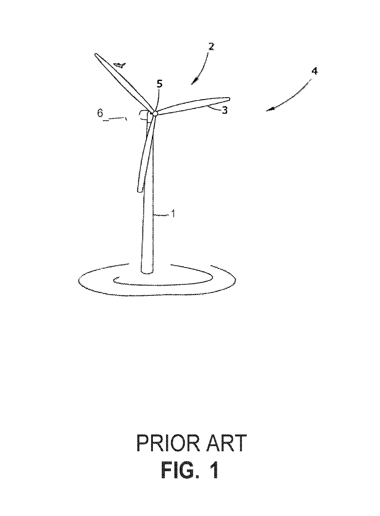
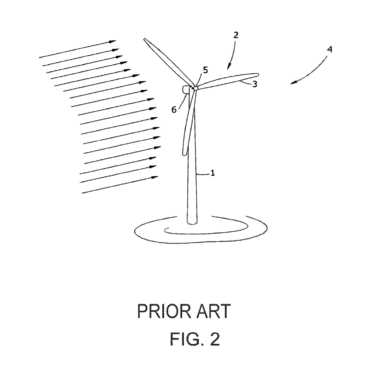
[0055]FIG. 1 is a perspective view of a conventional power-generation windmill in the prior art. Prior art electricity-generating windmills are only able to capture a small portion of the wind energy passing through them. Some of the reasons for this are explained below.

[0056]The blades of electricity-generating windmills turn in a circle, so it will be useful to think of the area within a complete rotation covered by the blades of a windmill, as they turn, as 360 degrees. The area of a blade can be seen in terms of the number of “degrees” within a 360-degree turn that the blade covers. For example, a blade which covers 4 degrees would cover 1 / 90 of the total area embraced by the blades as they turn. A blade which covers 1 degree would cover 1 / 360 of the total area embraced by the blades as they turn.

[0057]Electricity-generating windmills of the prior art generally include three blades, which each cover 2.5 to 3 degrees. Therefore, the total area embraced by the blades amounts to th...


PUM


Abstract

A wind energy generation turbine is built to take advantage of high winds in mountain passes and other areas of extreme wind velocity. A windmill section is raised high by support structures. Electricity generators are kept in the base of the windmill to reduce elevated weight. A nozzle or shroud channels wind into a narrow raceway to take advantage of the Venturi effect. Windmill blade tips housed within a circular raceway are strengthened by blade tip connectors and blade spar struts against high wind forces. Windmill blade angle and windmill wind facing are dynamically altered by computerized motors for maximum efficiency. Windmill blade angle and / or generator load maintain ratio of windmill blade tip speed to wind speed for efficiency. Turbine speed translation gears are able to decouple windmill from 60 Hz cycle or use water pumps and gravity to store energy at peak generation times.

Description

CLAIM OF PRIORITY BENEFIT[0001]This application claims the benefit of prior USPTO Utility application Ser. No. 14 / 791,274, filed 3 Jul. 2015 and is a Continuation-In-Part of said prior application.FIELD OF THE INVENTION[0002]The invention relates to wind turbines. Specifically, it relates a power-generating wind turbine especially suited for use in high winds.[0003]REFERENCES CITEDDOCUMENTDATE FILEDAUTHOR(S)5,202,672May 1992Nakamura, et. al.7,821,164February 2007Laskaris et. al.7,939,958 B2May 2008Todorof8,148,841November 2008Apthorp8,257,019 B2October 2010Cironi8,269,369 B2March 2011Todoroff8,282,353June 2006Russ et. al.8,338,979June 2011Bray8,403,786July 2009Bech8,459,872 B2October 2008Nies, et. al.8,502,403 B2January 2008Merswolke, et. al.8,585,367July 2009BechUS2012 / 0292912March 2008HaskellUS2013 / 0216381June 2011LiuDESCRIPTION OF RELATED ART[0004]The following references represent advances in the art, but none of these references incorporate all the features of the present inven...

Claims


Application Information

Patent Timeline
Patent Type & Authority Patents(United States)
IPC IPC(8): F03D7/02F03D9/28F03D1/04F03D15/00F03D9/00F03D9/45F03D9/25F03D1/06F03D80/80
CPCF03D7/0204F03D1/0666F03D1/0675F03D7/022F03D7/028F03D9/008F03D9/28F03D15/00F03D1/04Y02E10/725F05B2240/31F05B2240/313Y02B10/30Y02E10/721Y02E10/723Y02E10/72F03D1/0658
Inventor WILLIAMS, DARELL ALLEN
Owner WILLIAMS DARELL ALLEN
Why Eureka
Try Eureka