Voltage-based auto-correction of switching time

Active Publication Date: 2019-07-30
SHENZHEN GOODIX TECH CO LTD
View PDF13 Cites 7 Cited by
  • Summary
  • Abstract
  • Description
  • Claims
  • Application Information

AI Technical Summary

Benefits of technology

[0005]Embodiments of the present invention provides circuits, devices, and methods for correcting systematic offset or delay of a low-side switch in a switching voltage regulator. The offset or

Problems solved by technology

The offset or delay may cause glitches at the switching node of the switching voltage regulator.
The gli

Method used


Image

  • Voltage-based auto-correction of switching time
  • Voltage-based auto-correction of switching time
  • Voltage-based auto-correction of switching time

Examples


Embodiment Construction

[0040]In the following description, numerous specific details are provided for a thorough understanding of the present invention. However, it should be appreciated by those of skill in the art that the present invention may be realized without one or more of these details. In other examples, features and techniques known in the art will not be described for purposes of brevity.

[0041]It will be understood that the drawings are not drawn to scale, and similar reference numbers are used for representing similar elements. Embodiments of the invention are described herein with reference to functional block diagrams that are schematic illustrations of idealized embodiments (and intermediate structures) of the invention.

[0042]It will be understood that, when an element or component is referred to as “connected to” or “coupled to” another element or component, it can be connected or coupled to the other element or component, or intervening elements or components may also be present. In cont...


PUM


Abstract

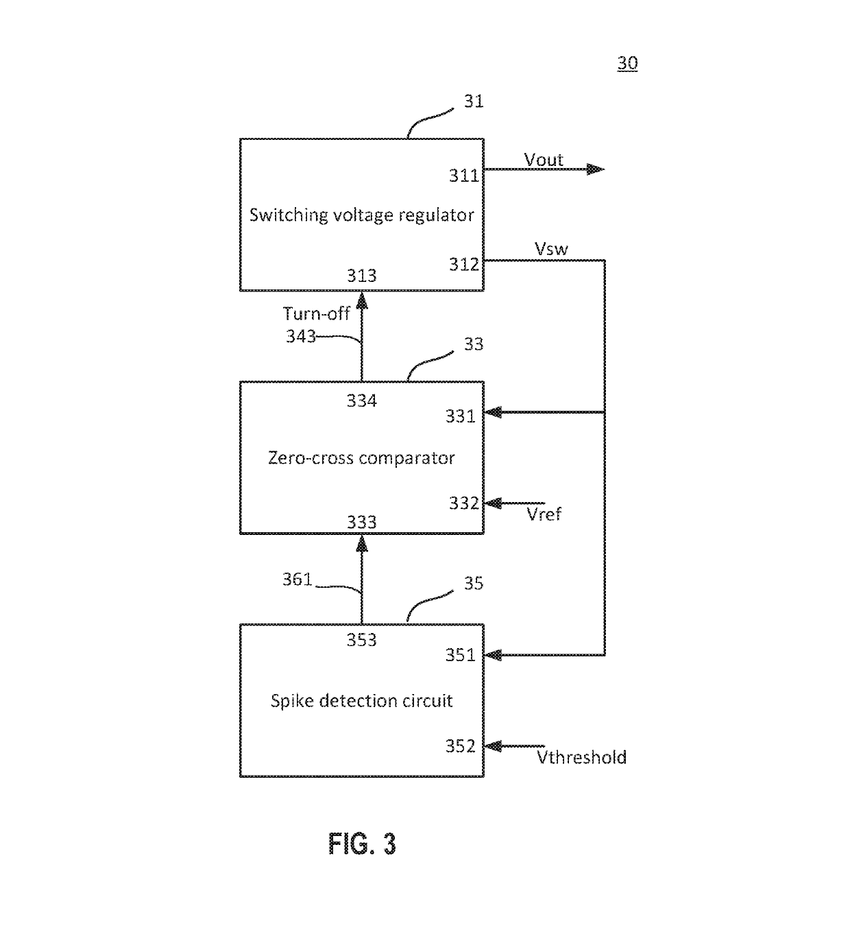
A control device for a switching voltage regulator having a high-side switch and a low-side switch to supply a switching voltage to a load includes a comparator configured to compare the switching voltage with a reference voltage to provide an enable signal to the low-side switch, and a spike detection circuit configured to receive the switching voltage and output an offset control signal to execute a time shift to the enable signal.

Description

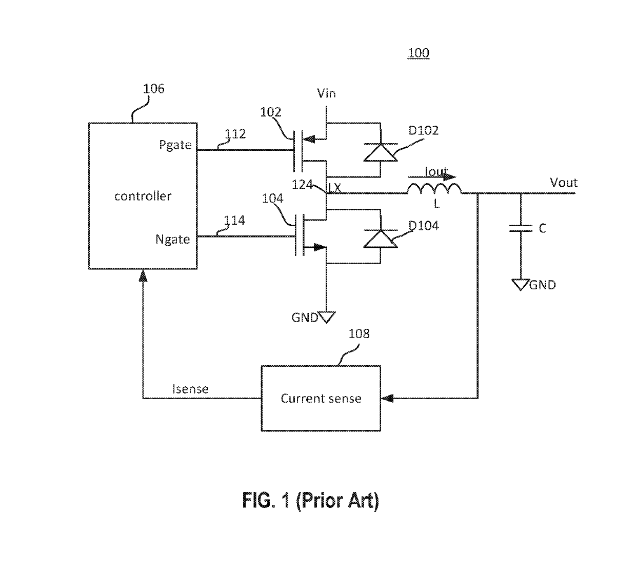
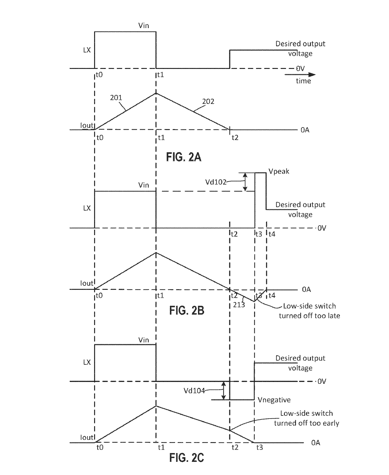
FIELD OF THE INVENTION[0001]The present invention relates generally to switching regulators. More particularly, embodiments of the present invention relate to control circuits, devices, and methods of detecting and eliminating the presence of spikes at a switching node of the switching regulators and optimizing a dead time in a switching module of the switching regulators.BACKGROUND OF THE INVENTION[0002]Voltage regulators have been employed for providing stable supply voltages to a large variety of electronic products. FIG. 1 schematically shows a switching voltage regulator 100, which includes a high-side switch 102 and a low-side switch 104 connected between an input voltage Vin and ground GND to be alternatively switched by a controller 106, a current sense circuit 108 senses an output current Iout flowing through an inductor L to charge a capacitor C to produce an output voltage Vout. Current sense circuit 108 senses the output current Iout to provide a current Isense to contro...

Claims


Application Information

Patent Timeline
IPC IPC(8): H02M3/156H02M1/08H03K5/1536H02M3/157H03K5/24H02M3/158H03K5/00H02M1/00
CPCH02M3/158H02M1/08H02M3/157H03K5/1536H03K5/2481H03K2005/00195H02M2001/0048H03K2005/00026H03K2005/0028H02M3/1584H02M3/1588Y02B70/10H02M1/385H02M1/0048
Inventor YAZDI, SIAVASHHUSSIEN, FAISAL
Owner SHENZHEN GOODIX TECH CO LTD
Why Eureka
Try Eureka