Slip ring assembly

Active Publication Date: 2014-12-25
WOBBEN PROPERTIES GMBH
View PDF15 Cites 3 Cited by
  • Summary
  • Abstract
  • Description
  • Claims
  • Application Information

AI Technical Summary

Benefits of technology

[0011]One or more embodiments of the present invention may address at least one of the above-mentioned problems. In particular one embodiment seeks to provide a solution in which slip ring transmitters of the ‘gold wire’ type, that is to say slip ring tr

Problems solved by technology

Hitherto, in the case of a worn slip ring transmitter involving gold wire technology, the gold wire board and the slip ring would generally have had to be replaced

Method used


Image

  • Slip ring assembly
  • Slip ring assembly
  • Slip ring assembly

Examples


Embodiment Construction

[0029]Hereinafter the same references can denote similar but non-identical elements to emphasize the functional relationship of those elements.

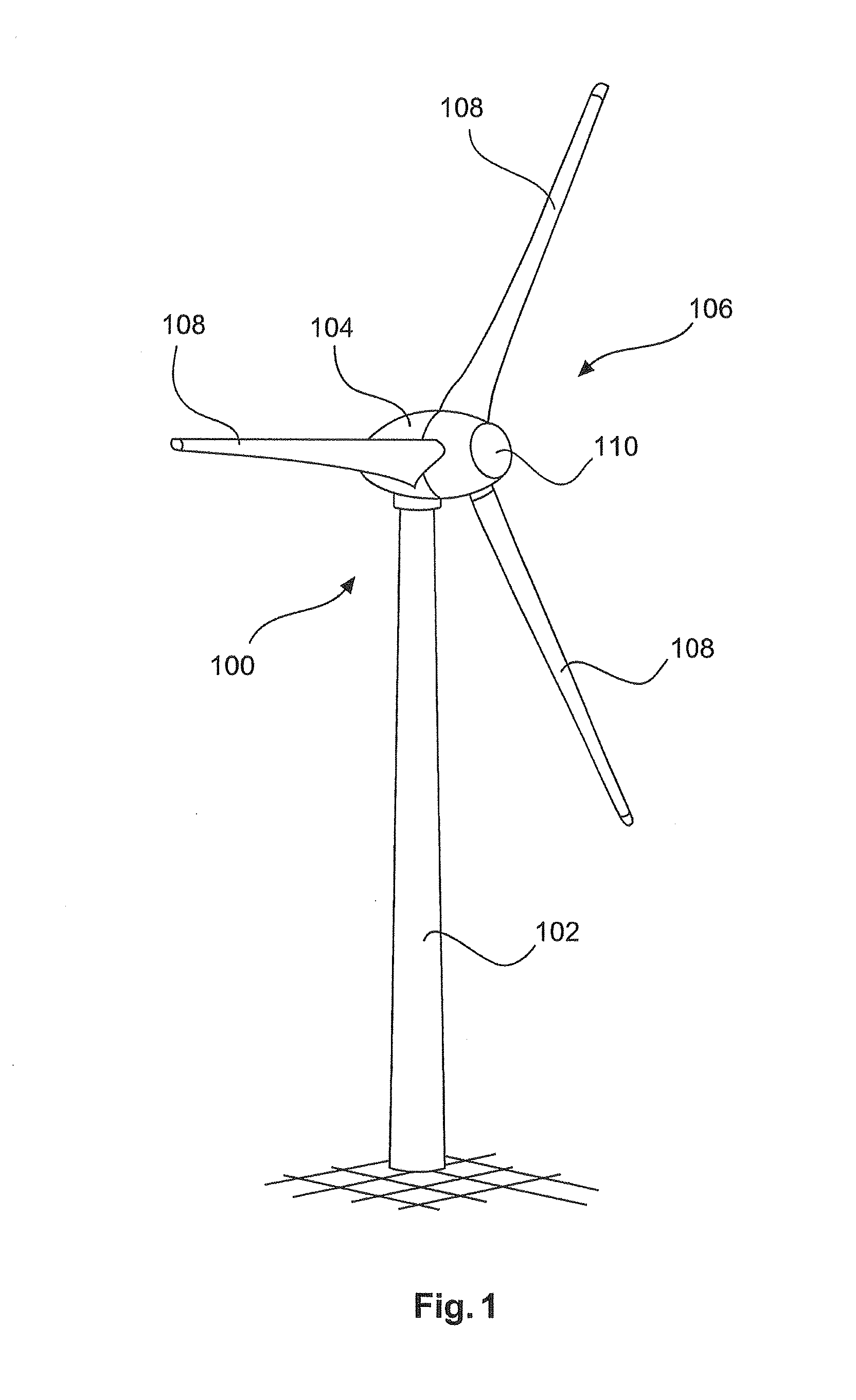
[0030]FIG. 1 shows a wind power installation 100 comprising a pylon 102 and a pod 104. Arranged at the pod 104 is a rotor 106 having three rotor blades 108 and a spinner 110. In operation the rotor 106 is caused to rotate by the wind and thereby drives a generator in the pod 104.

[0031]FIG. 1 shows a gearless wind power installation 100 which uses a slip ring transmitter to transmit electric signals from the stationary part of the pod 104 to the rotor 106, namely in particular the spinner 110. The illustrated wind power installation uses an externally excited synchronous generator for which the exciter current is transmitted from the stationary part of the pod 104 to the spinner 110 by way of the slip ring transmitter. In addition the illustrated wind power installation 100 has rotor blades 108 which are adjustable in their angle of incidence....


PUM

PropertyMeasurementUnit
Transmissionaaaaaaaaaa

Abstract

The invention concerns a method of reconditioning a slip ring transmitter of the gold wire type which has a slip ring, in particular a gold ring, for use with a gold wire board as the circuit board, including the steps: removing a gold wire board from the slip ring transmitter, and fitting a multi-brush board as a replacement for the gold wire board.

Description

BACKGROUND[0001]1. Technical Field[0002]The present invention concerns a slip ring transmitter and a method of reconditioning a slip ring transmitter. The present invention further concerns a wind power installation having a slip ring transmitter.[0003]2. Description of the Related Art[0004]Wind power installations are generally known and a typical installation is shown in FIG. 1. There the aerodynamic rotor rotates in usual operation relative to the stationary part of the pod, being driven by wind. To exchange electric energy or electric signals from the stationary part to the rotating part, namely the rotor, a slip ring transmitter is usually provided. In particular energy can be transmitted to so-called pitch motors which can adjust the rotor blades of the rotor in their angle of incidence. In addition for example energy can be transmitted for an electric blade heating system, if provided.[0005]A particularity applies for gearless wind power installations which use an externally ...

Claims


Application Information

Patent Timeline
IPC IPC(8): H01R43/14H01R43/10H02K13/00F03D9/00H01R39/08
CPCH01R43/14F03D9/002H01R43/10H02K13/003H01R39/08H01R39/24F03D9/25Y10T29/49011F03D15/20Y02E10/72Y02P70/50
Inventor BEEKMANN, ALFRED
Owner WOBBEN PROPERTIES GMBH
Why Eureka
Try Eureka