
Cookware and geometrically patterned magnetic stirrer assembly

a magnetic stirrer and geometric pattern technology, applied in the direction of cooking vessels, electric/magnetic/electromagnetic heating, intergral heating vessels, etc., can solve the problems of slow cookers relying on a slow, low and even cooking rate to function, thermal stress and ultimately cracking of ceramics, etc., to enhance stirring and mixing of contents.

Inactive Publication Date: 2019-08-06
RYAN DEBORAH
View PDF10 Cites 24 Cited by
  • Summary
  • Abstract
  • Description
  • Claims
  • Application Information

AI Technical Summary

Benefits of technology

This patent describes a magnetic stirrer that can be controlled to follow different patterns, speeds, and directions, optimizing the stirring process. The stirrer can move in both forward and reverse patterns, and it can be adjusted to different temperatures and timers. The device can also be controlled remotely through Wi-Fi or radio frequency. The main technical effect of this patent is to provide a magnetic stirrer that can enhance the stirring and mixing of cookware contents in a geometrically patterned way. The controller allows for independent regulation of the speed and direction of the stirrer and the heat generated by the heating element, so that the stirrer can operate while no heating is taking place, and vice versa.

Problems solved by technology

Typically, slow cookers rely on a slow, low and even rate of cooking to function.
Due to the slow cooking nature of the device, the contents of the ceramic need not be constantly monitored in order to prevent burning.
In addition, the relatively low power and even distribution of heat of the slow cooker prevents hot spots from forming in the ceramic, which could lead to thermal stresses and ultimately cracking of the ceramic.
The limited size of some stirring bars limits magnetic stirrers to non-viscous liquids.
The problem with these assemblies is that they do not automate the stirring process through use of electromagnetic coils.
Also, the stirrer is not adaptable to follow various patterns, speeds, and directions, so as to optimize stirring.

Method used


Image

  • Cookware and geometrically patterned magnetic stirrer assembly
  • Cookware and geometrically patterned magnetic stirrer assembly
  • Cookware and geometrically patterned magnetic stirrer assembly

Examples


Embodiment Construction

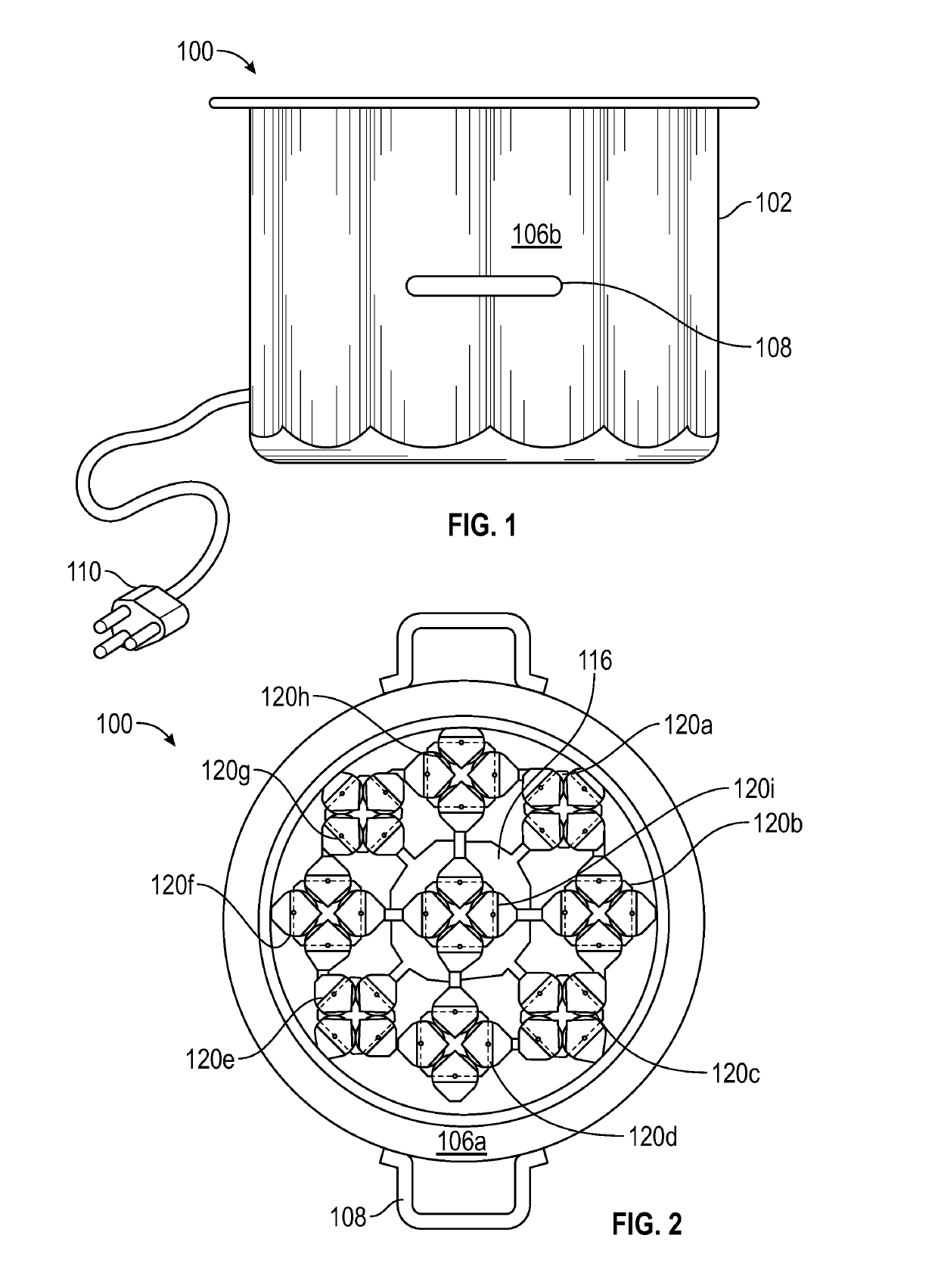
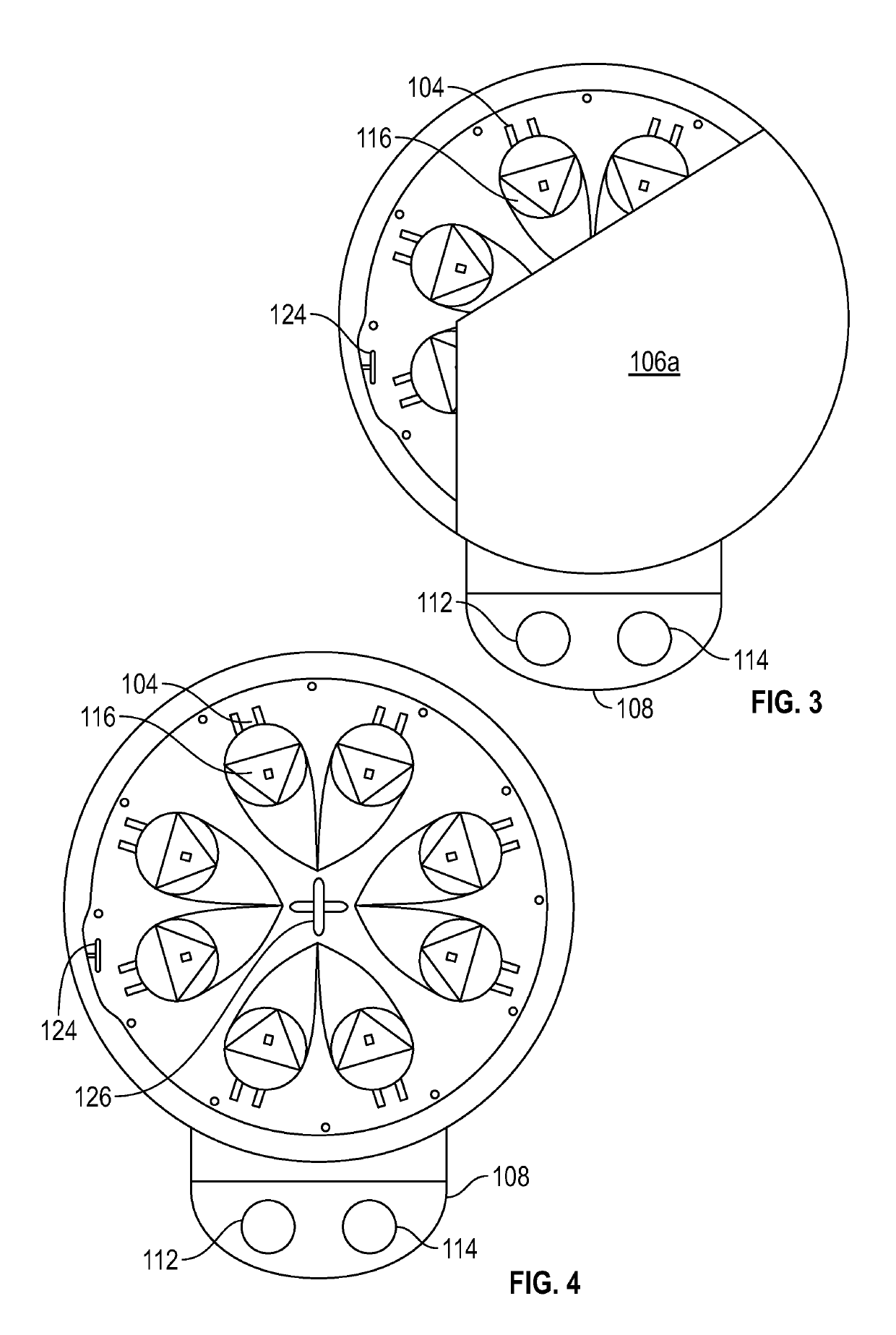
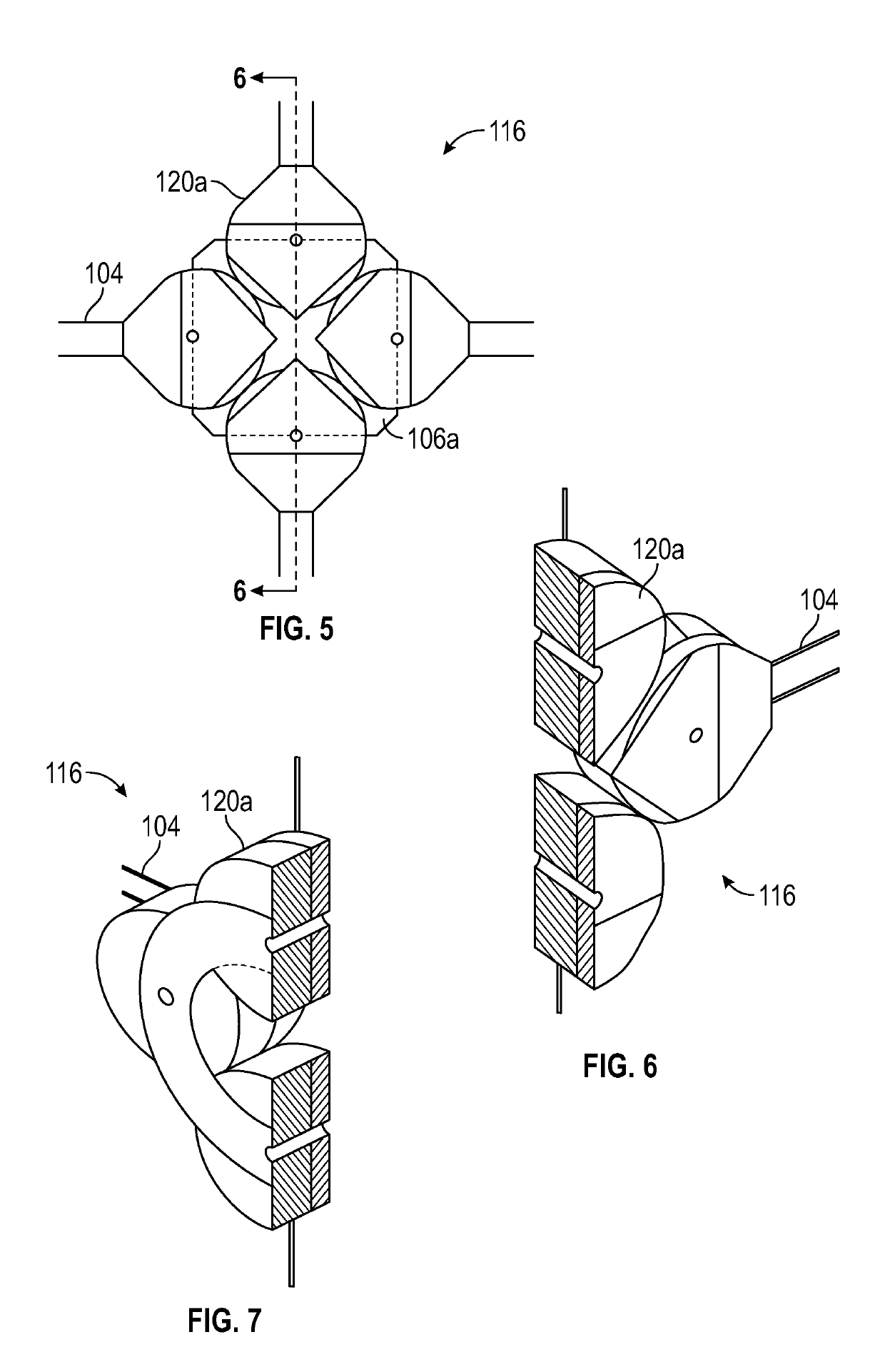
[0063]The following detailed description is merely exemplary in nature and is not intended to limit the described embodiments or the application and uses of the described embodiments. As used herein, the word “exemplary” or “illustrative” means “serving as an example, instance, or illustration.” Any implementation described herein as “exemplary” or “illustrative” is not necessarily to be construed as preferred or advantageous over other implementations. All of the implementations described below are exemplary implementations provided to enable persons skilled in the art to make or use the embodiments of the disclosure and are not intended to limit the scope of the disclosure, which is defined by the claims. For purposes of description herein, the terms “upper,”“lower,”“left,”“rear,”“right,”“front,”“vertical,”“horizontal,” and derivatives thereof shall relate to the invention as oriented in FIG. 1. Furthermore, there is no intention to be bound by any expressed or implied theory pres...


PUM


Abstract

A cookware and geometrically patterned magnetic stirrer assembly provides cookware for heating and stirring food. A heating element heats a cooking surface on the cookware. At least one geometrically patterned electromagnetic coil is integrated into the cookware. The electromagnetic coil generates a magnetic field when an electrical current passes through. At least one magnetic stirrer operates on the cooking surface to stir the food in response to the magnetic field, in accordance to the path of geometric pattern. Controllably applying varying electrical currents through the electromagnetic coil moves the magnetic stirrer in the path of the geometric pattern at varying speeds and directions. The electromagnetic coil can be arranged in a snowflake pattern, a spider web pattern, or a helix. A controller regulates electrical current through the heating element and the electromagnetic coil to allow the heating and stirring functions to operate independently of each other.

Description

CROSS REFERENCE OF RELATED APPLICATIONS[0001]This application claims the benefits of U.S. provisional application No. 62 / 441,260, filed Dec. 31, 2016 and entitled ELECTRIC COOKER WITH ELECTROMAGNETIC STIRRER which provisional application is incorporated by reference herein in its entirety.FIELD OF THE INVENTION[0002]The present invention relates generally to a cookware and geometrically patterned magnetic stirrer assembly. More so, the present invention relates to a cookware and stirring assembly that integrates a heating element and a geometrically patterned electromagnetic coil into a cookware to heat food and control the stirring pattern of at least one magnetic stirrer; whereby varying electrical currents are applied to the geometrically patterned electromagnetic coil to produce at least one magnetic field through the cooking surface of the cookware, so as to induce the magnetic stirrer to move substantially along the geometric pattern of the electromagnetic coils in controllabl...

Claims


Application Information

Patent Timeline
Patent Type & Authority Patents(United States)
IPC IPC(8): A47J27/00A47J36/16A47J43/046B01F13/08B01F15/00H05B6/12A47J36/32
CPCA47J27/004A47J36/165A47J43/0465B01F15/00389H05B6/1209B01F13/0818A47J36/32B01F33/452B01F35/221422
Inventor RYAN, DEBORAH
Owner RYAN DEBORAH
Learn More