
Method and apparatus for in vitro kidney organogenesis

a kidney and organogenesis technology, applied in the field of kidney organogenesis methods and apparatuses, can solve the problems of permanent loss of kidney function, limited option, and high cos

Active Publication Date: 2019-08-06
RGT UNIV OF CALIFORNIA +1
View PDF15 Cites 4 Cited by
  • Summary
  • Abstract
  • Description
  • Claims
  • Application Information

AI Technical Summary

Problems solved by technology

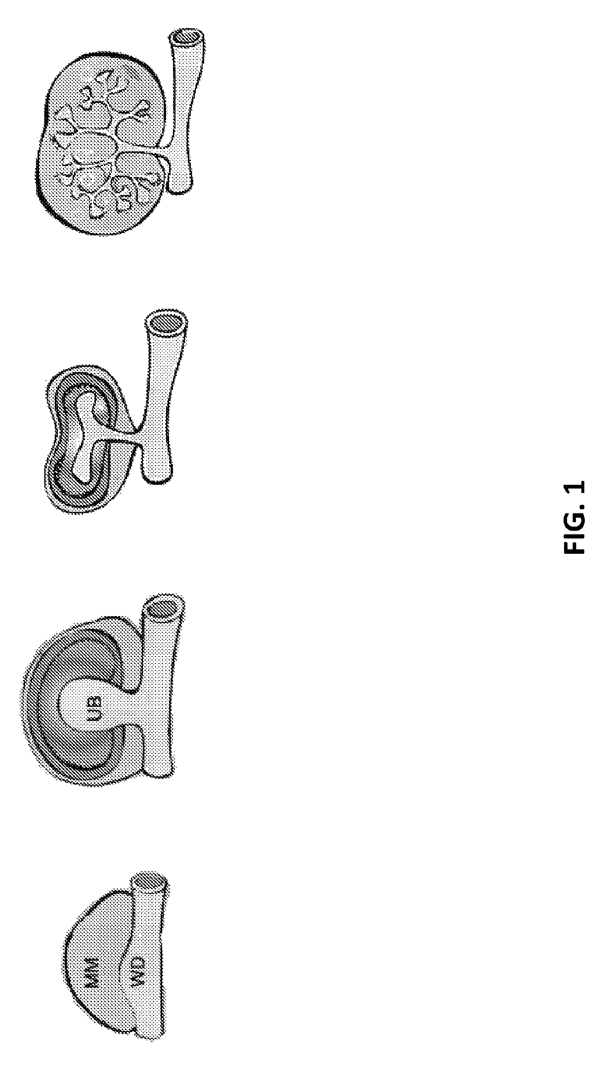
End stage renal disease (ESRD), the permanent loss of kidney function, is an increasing threat to healthcare across all societies worldwide.
Currently, the preferred treatment for ESRD is kidney transplantation, but this option is limited by the shortage of donor organs and complications due to rejection and immunosuppression.
Dialysis, the second treatment option for ESRD, is cost intensive and associated with morbidity as well as poor quality of life.
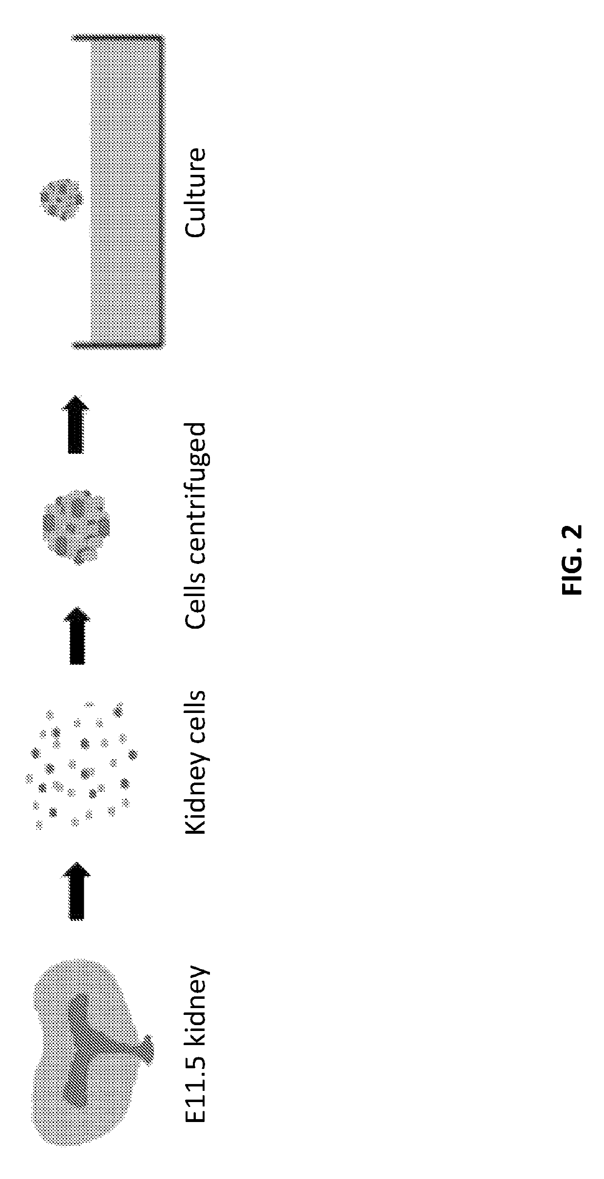
These experiments, however, also showed that the self-organization potential of the renal progenitor cells is limited.
Since a major function of the kidney is the filtration of blood and the draining of waste product through a centralized collecting duct system, this conventional re-aggregation method is not sufficient to develop into a functional organ.

Method used


Image

  • Method and apparatus for in vitro kidney organogenesis
  • Method and apparatus for in vitro kidney organogenesis
  • Method and apparatus for in vitro kidney organogenesis

Examples


experimental examples

[0083]The invention is further described in detail by reference to the following experimental examples. These examples are provided for purposes of illustration only, and are not intended to be limiting unless otherwise specified. Thus, the invention should in no way be construed as being limited to the following examples, but rather, should be construed to encompass any and all variations which become evident as a result of the teaching provided herein.

[0084]Without further description, it is believed that one of ordinary skill in the art can, using the preceding description and the following illustrative examples, make and utilize the compounds of the present invention and practice the claimed methods. The following working examples therefore, specifically point out the preferred embodiments of the present invention, and are not to be construed as limiting in any way the remainder of the disclosure.

example 1

ranching in a T-Shape Kidney Mold Device

[0085]FIG. 8A-E depict the UB tube 20 growing into MM / SC 50 in the MM cell chamber 36 with branching morphogenesis. In FIG. 8B, the end of UB tube 20 that is not in contact with the MM cell chamber remains unbranched. When sufficient branching morphogenesis of the UB tube 20 has occurred within the MM cell chamber 36, as illustrated in FIGS. 8D and E, the embryonic kidney organoid can be removed from the kidney mold by pipette or forceps and implanted into a mammalian subject for further development.

example 2

in a Circular Kidney Mold Device

[0086]FIG. 11A-11B depict the generation of an embryonic kidney organoid without using a precursor micromold. UB cells were seeded directly into the UB cell chamber of a kidney mold device having a plug in the MM cell chamber. FIG. 11A shows the kidney mold device with a rudimentary UB tube (immunostained green) after the plug has dissolved, with a MM / SC aggregate placed in the MM cell chamber. Note that in FIG. 11A, no UB cells are present in the MM cell chamber due to the use of the plug. FIG. 11B shows that branching morphogenesis has begun with the UB tube extending into the MM / SC aggregate.


PUM

PropertyMeasurementUnit
widthaaaaaaaaaa
widthaaaaaaaaaa
widthaaaaaaaaaa

Abstract

The invention provides for a device, system, and methods for using the same with kidney progenitor cells, specifically ureteric bud (UB) cells, metanephric mesenchymal (MM) cells, and the stromal cell (SC) subpopulation of the metanephric mesenchyme, to generate an embryonic kidney organoid that can be implanted into a mammalian subject to create a living, functional kidney.

Description

CROSS-REFERENCE TO RELATED APPLICATIONS[0001]This application is the U.S. national phase application filed under 35 U.S.C. § 371 claiming benefit to International Patent Application No. PCT / US15 / 17726, filed Feb. 26, 2015, which is entitled to priority under 35 U.S.C. § 119(e) to U.S. Provisional Patent Application No. 61 / 945,022, filed Feb. 26, 2014, each of which application is hereby incorporated herein by reference in its entirety.BACKGROUND OF THE INVENTION[0002]End stage renal disease (ESRD), the permanent loss of kidney function, is an increasing threat to healthcare across all societies worldwide. Currently, the preferred treatment for ESRD is kidney transplantation, but this option is limited by the shortage of donor organs and complications due to rejection and immunosuppression. Dialysis, the second treatment option for ESRD, is cost intensive and associated with morbidity as well as poor quality of life.[0003]Regenerative medicine is working towards developing methods to...

Claims


Application Information

Patent Timeline
Patent Type & Authority Patents(United States)
IPC IPC(8): A61L27/36C12M3/00C12M1/12C12M3/06C12M1/00C12N5/071
CPCA61L27/3604A61L27/3683C12M21/08C12M23/58C12M25/14C12N5/0697C12M23/16C12N2502/256
Inventor YANAGAWA, NORIMOTONISHIKAWA, MASAKIHAMON, MORGANHAUSER, PETER VIKTOR
Owner RGT UNIV OF CALIFORNIA
Learn More