Onboard DC charging circuit using traction drive components

Active Publication Date: 2019-08-06
GM GLOBAL TECH OPERATIONS LLC
View PDF7 Cites 13 Cited by
  • Summary
  • Abstract
  • Description
  • Claims
  • Application Information

AI Technical Summary

Benefits of technology

The present disclosure relates to an onboard DC charging circuit for electric vehicles that allows for backward compatibility with legacy off-board DC fast-charging stations. The circuit incorporates traction drive components and power inverter modules to ensure the battery pack can be charged to its maximum capacity. The circuit includes an RESS and a switching module with additional switches that selectively connect the battery pack to the PIM. The controller selectively establishes a DC-DC boost mode of the PIM based on the maximum voltage capacity of the battery pack and the maximum charging voltage of the off-board DC fast-charging station. The circuit can be used in various electric vehicle configurations and can also include an accessory module for supplying power to other vehicle systems. The technical effect of the invention is to ensure the battery pack can be fully charged without exceeding the limits of the off-board DC fast-charging station.

Problems solved by technology

As a result of this trend, a given DC fast-charging station may be incapable of fully charging certain high-voltage battery packs.
However, emerging battery packs may be rated for 800-1000 VDC or higher, and thus are unable to achieve a full state of charge at such charging levels.

Method used


Image

  • Onboard DC charging circuit using traction drive components
  • Onboard DC charging circuit using traction drive components
  • Onboard DC charging circuit using traction drive components

Examples


Embodiment Construction

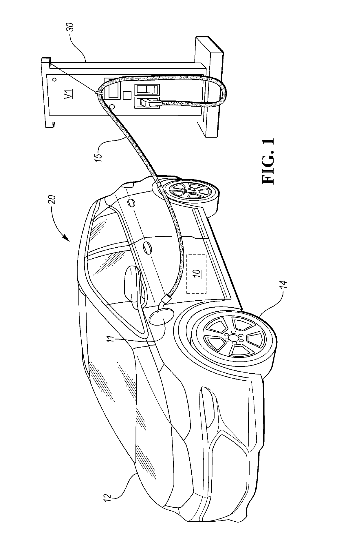
[0021]Referring to the drawings, wherein like reference numbers refer to the same or like components in the several Figures, a direct current (DC) charging circuit 10 is shown schematically in FIG. 1 as part of a motor vehicle 20. The vehicle 20 is depicted as undergoing a DC fast-charging operation in which the DC charging circuit 10 is electrically connected to an off-board DC fast-charging station 30 via a charging port 11 and a charging cable 15, e.g., using an SAE J1772 charge connector, CHAdeMO, or another suitable regional or national standard charging plug or connector. The present teachings are independent of the particular charging standard that is ultimately employed in a DC fast-charging operation involving the DC fast-charging station 30, and thus the above-noted examples are merely illustrative.

[0022]The DC charging circuit 10 may be beneficially used as part of the motor vehicle 20, as well as other electrical systems such as stationary or mobile power plants robots o...


PUM


Abstract

A DC charging circuit has a pair of switches and a battery pack with a maximum voltage capacity, and a power inverter module (PIM). The pair of switches connects / disconnects the battery pack to / from the PIM. An electric machine has phase windings sharing a motor neutral terminal. The phase windings are electrically connected to respective switching pair of the PIM. A switching module has one or two additional switches selectively connecting the PIM to the station, and a center switch selectively connecting the station to the motor neutral terminal. A controller executes a method that establishes a boost mode of the PIM when the maximum voltage capacity exceeds the maximum charging voltage. The boost mode is established by closing the pair of switches of the RESS, closing the center switch of the switching module and one of the additional switches, and opening the other additional switch if present.

Description

INTRODUCTION[0001]An electric powertrain typically includes one or more polyphase / alternating current (AC) electric machines. The phase windings of each electric machine are energized via a power inverter by a high-voltage direct current (DC) battery pack. Switching control of semiconductor switching pairs within the power inverter ultimately generates an AC output voltage suitable for energizing the phase windings, and for ultimately inducing torque-producing machine rotation. The battery packs used in modern plug-in electric or hybrid electric vehicles or other mobile or stationary high-voltage systems may be recharged by connecting the battery pack to an off-board power supply via an onboard charging port.[0002]When the off-board power supply produces an AC charging voltage, an AC-DC converter is used aboard the vehicle to convert the AC charging voltage to a DC voltage suitable for storage in the individual battery cells of the battery pack. The converter may include a passive d...

Claims


Application Information

Patent Timeline
IPC IPC(8): B60L53/30B60L53/20B60L58/12H02J7/00B60L53/14
CPCH02J7/0021H02J7/0004H02J7/0027B60L53/14B60L53/20B60L53/30B60L58/12H02J7/02H02J2310/48H02J7/0047H02J7/0013H02J7/00036H02J7/00047Y02T90/16Y02T10/92Y02T10/70Y02T90/14Y02T10/7072Y02T90/12
Inventor CONLON, BRENDAN M.
Owner GM GLOBAL TECH OPERATIONS LLC
Why Eureka
Try Eureka