
Shuttle valve

a valve and valve body technology, applied in the field of valves, can solve the problems of mixing of fluid in the initial ports, not allowing easy backflow of fluid, etc., and achieve the effects of reducing the fluid flow rate requirements, reducing the vacillation of the port blocking mechanism, and facilitating fluid backflow

Active Publication Date: 2019-08-06
THE SUBSEA
View PDF9 Cites 2 Cited by
  • Summary
  • Abstract
  • Description
  • Claims
  • Application Information

AI Technical Summary

Benefits of technology

[0008]The primary advantage of the invention is to provide an improved shuttle valve that retards fluid flow from more than one of a plurality of inlet ports.
[0009]Another advantage of the invention is to provide a shuttle valve that reduces vacillation of the port blocking mechanism while under pressure.
[0010]Another advantage of the invention is to provide a shuttle valve that more easily allows fluid backflow though a particular inlet port while not under pressure.
[0011]Another advantage of the invention is to provide a shuttle valve that reduces fluid flow rate requirements to block all but one inlet port.
[0012]Other objects and advantages of the present invention will become apparent from the following descriptions, taken in connection with the accompanying drawings, wherein, by way of illustration and example, an embodiment of the present invention is disclosed.
[0013]In accordance with a preferred embodiment of the invention, there is shown a shuttle valve assembly having a housing with a plurality of inlet ports and an outlet port for fluid flow; the housing having a passageway for fluid to flow from any one of said plurality of inlet ports to the outlet port; each of the plurality of inlet ports has an associated plunger; the plurality of plungers configured one to the other such that when sufficient pressurized fluid is flowing into any one of the plurality of inlet ports, fluid is prevented from flowing into any other of the plurality of inlet ports; and one or more of the plurality of plungers includes a male portion and a female portion mated together.

Problems solved by technology

Often, once a supplemental fluid is introduced into a shuttle valve, fluid in the initial ports becomes mixed due to design flaws or inherent problems with the shuttle valves, while the fluid being transmitted to cause actuation is separated.
Due to the extreme fluid pressures with which these types of shuttle valves are used, the existing shuttle valves are subject to vacillations, where the valve rapidly moves back and forth within the housing, sometimes resulting in breakage.
In addition, existing shuttle valves do not allow for easy backflow of fluid through an inlet port such that an inlet port may be designated as a return to surface port to allow controlled fluid flow when the system is no longer pressurized.

Method used


Image

  • Shuttle valve
  • Shuttle valve

Examples


Embodiment Construction

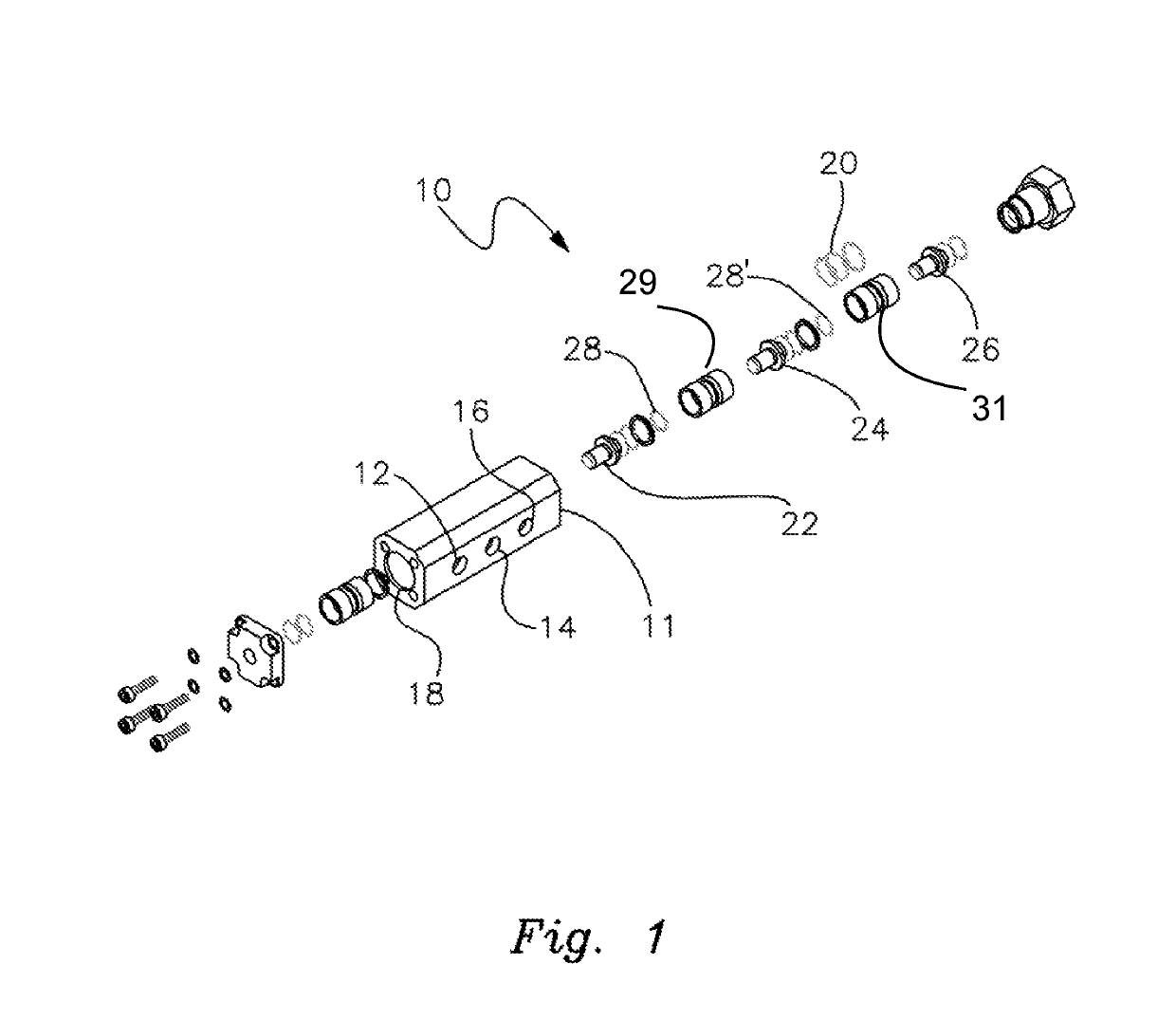
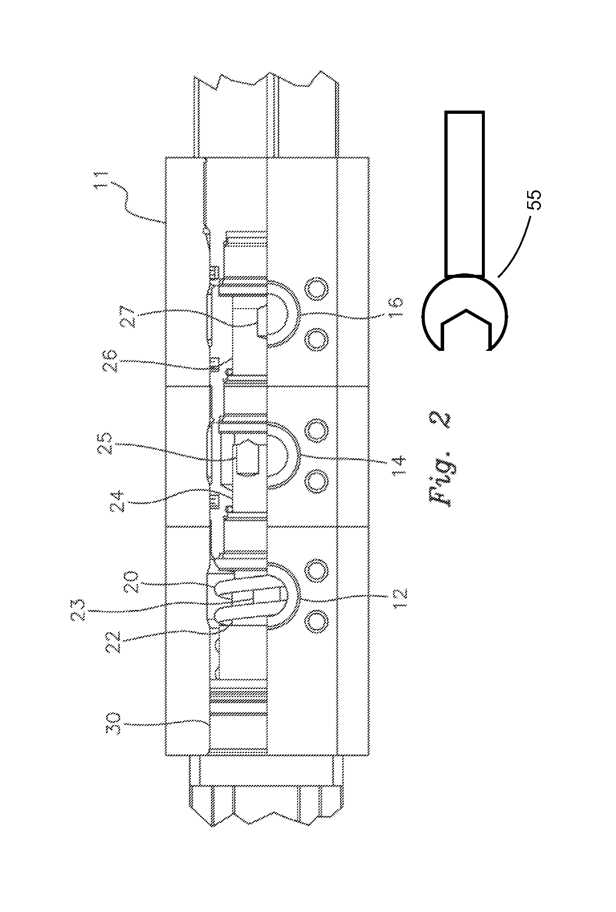
[0019]Referring now to FIG. 1, an exploded view of a shuttle valve 10 is illustrated. Shuttle valve 10 includes a housing 11, which has first inlet port 12, second inlet port 14, third inlet port 16, and outlet port 18. Shuttle valve 10 also includes a spring apparatus 20, designed to create tension between outlet port 18 and first inlet port 12, though the position of the spring may be to bias any one of inlet ports 12, 14 or 16. Outlet port 18 is separated from first inlet port 12 via a radial seal (not shown). First inlet port 12 is separated from second inlet port 14 via a radial seal 28. Second inlet port 14 is separated from third inlet port 16 via a second radial seal 28′. Each of first inlet port 12, second inlet port 14 and third inlet port 16 includes an associated spool and a plunger arrangement. Plungers 22, 24, and 26 of each port are in communication with respective spools in a male-female mating relationship and are positioned between an immovable member and outlet po...


PUM


Abstract

A shuttle valve has a housing with a plurality of inlet ports, an outlet port for fluid flow, and a passageway for fluid to flow from any one of the inlet ports to the outlet port. Each Inlet port has an associated plunger configured one to the other such that when sufficient pressurized fluid is flowing into any one of the inlet ports, fluid is prevented from flowing into any other inlet port. The plungers include male and female mating portions with a radial seal between them. A biasing spring allows one of the plungers to allow backward fluid flow through the associated inlet port when not under pressure.

Description

CROSS REFERENCE TO RELATED APPLICATIONS[0001]This application is based on provisional patent application No. 61 / 389,343 entitled “Shuttle Valve” filed on Oct. 4, 2010, which is hereby incorporated by reference as if fully set forth herein.BACKGROUND OF THE INVENTION[0002]The present invention relates to valves and more particularly to a shuttle valve for use in subsea applications and other desired locations.[0003]A shuttle valve is a type of valve that allows fluid to flow through it from one of two or more sources. In the basic, two-source structure, a shuttle valve is like a tube with three openings, two for fluid inflow and one for fluid outflow. A blocking valve element moves freely within the tube such that when pressure from a fluid is exerted through a first fluid inlet opening, it pushes the blocking valve towards the other fluid inflow opening, which prevents the fluid from travelling through that opening, but allows it to flow through the first inlet to the outlet. In thi...

Claims


Application Information

Patent Timeline
Patent Type & Authority Patents(United States)
IPC IPC(8): F16K11/07F15B13/02
CPCF16K11/07F15B13/028Y10T137/87692Y10T137/2569F16K3/314F16K11/10
Inventor MCMILES, BARRY J
Owner THE SUBSEA
Learn More