

Livestock management system and management method for livestock
a management system and livestock technology, applied in the field of livestock management system and management method, can solve problems such as difficult management, and achieve the effect of easy managemen
- Summary
- Abstract
- Description
- Claims
- Application Information
AI Technical Summary
Benefits of technology
Problems solved by technology
Method used
Image

Examples
first embodiment
[0056][Outline of Livestock Management System]
[0057]A livestock management system according to this embodiment is, for example, a system that can be utilized by an employee (user) of a stock-raising farmer or stock-raising facilities, and is configured to be capable of performing stay monitoring processing of monitoring a region in which a livestock animal is staying within the stock-raising facilities.
[0058]In the following description, staying in a certain region refers to the presence of a livestock animal within that region for a predetermined time or more. The predetermined time is not particularly limited, and is set to, for example, several minutes to several hours.
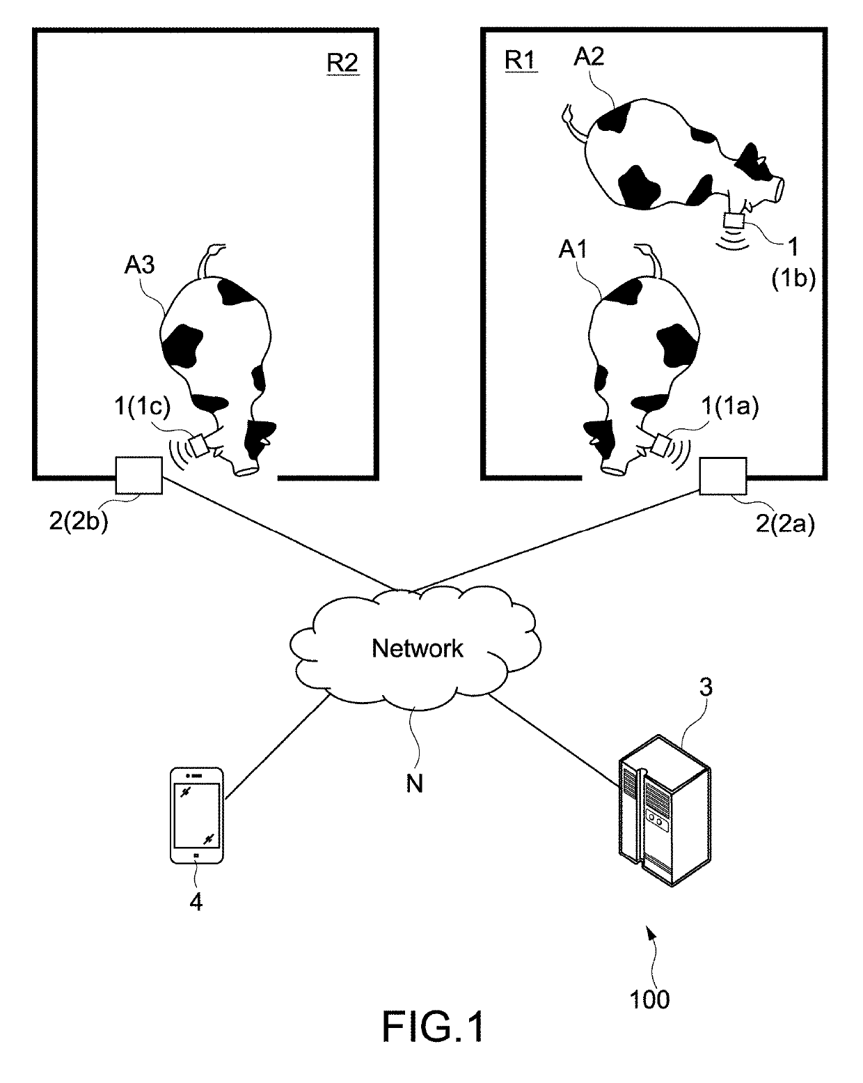
[0059]FIG. 1 is a schematic diagram showing a schematic configuration of a livestock management system of a first embodiment of the present technology.
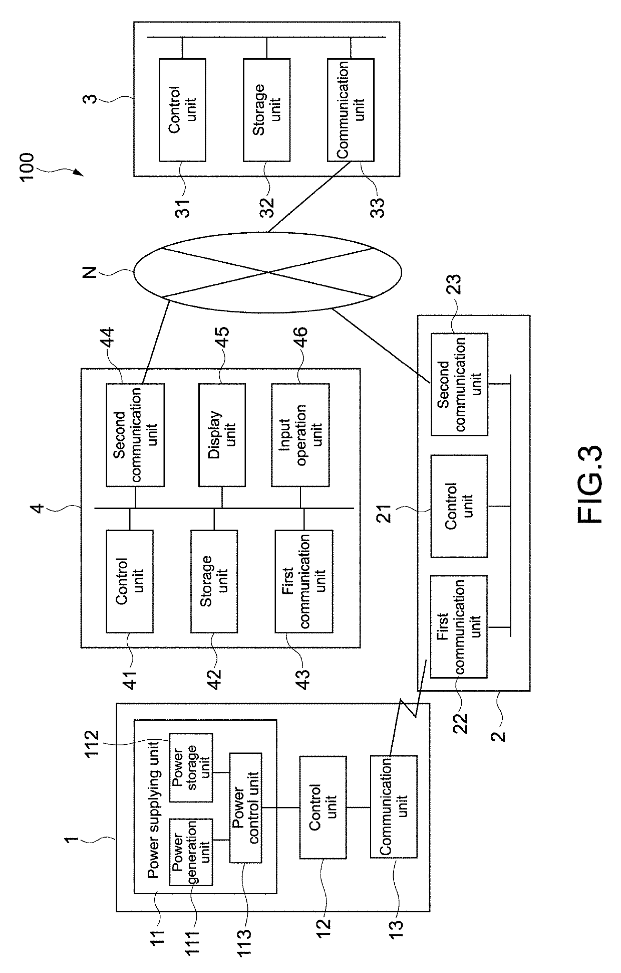
[0060]As shown in the figure, a livestock management system 100 includes a plurality of transmission apparatuses 1 (transmission apparatuses 1a, 1b, 1c), a...
operation example
[0195]FIG. 7 is a flowchart showing an operation example of registration processing of the livestock management system 100.
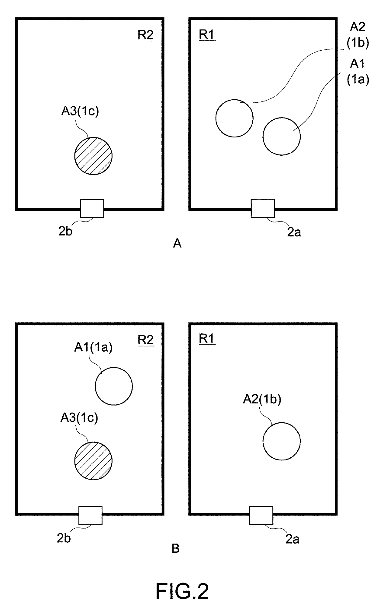
[0196]In this operation example, an example in which the individual identification signal is transmitted to the communication apparatus 2b from a transmission apparatus 1a attached to the livestock animal A1 of B of FIG. 2 will be described.
[0197]Note that, in the figure, processing of ST101 to ST104 is executed by the transmission apparatus 1, processing of ST201 to ST206 is executed by the communication apparatus 2, processing of ST301 to ST306 is executed by the server apparatus 3, and processing of ST401 to ST402 is executed by the terminal apparatus 4.
[0198]First of all, if the transmission apparatus 1a satisfies a predetermined condition (ST101), the transmission apparatus 1a transmits an individual identification signal including an individual identifier for identifying the transmission apparatus 1a (ST102). The predetermined condition set forth herein ma...
modified example 1-1
Case where Correspondence Pattern of Communication Apparatus and Region is (ii)
[0229]In the above-mentioned operation example, the case where the correspondence pattern of the communication apparatus and the region is (i) the pattern in which there are a plurality of regions and one communication apparatus 2 corresponds to each region has been described. Now, the case where it is (ii) the pattern in which there are a plurality of regions and a plurality of communication apparatuses 2 correspond to each region will be described.
[0230]FIG. 10 is a schematic diagram showing a position relationship between each region and the communication apparatus 2 according to Modified Example 1-1.
[0231]In the figure, as in FIG. 2, the livestock animals A1 to A3 are managed in the plurality of regions R1, R2 of the stock-raising facilities.
[0232]The communication apparatuses 2a, 2b are arranged in the entrance of the region R1 and communication apparatuses 2c, 2d are arranged in the entrance of the ...
PUM
 Abstract
Description
Claims
Application Information