Nitriding process method of steel member

a technology of nitriding process and steel member, which is applied in the direction of furnaces, heat treatment equipment, manufacturing tools, etc., can solve the problems of uneven generation of nitride compound layer over the positions of components, and productivity problems, and achieve high pitting resistance and bending fatigue strength

Active Publication Date: 2019-08-20
DOWA THERMOTECH +1
View PDF9 Cites 1 Cited by
  • Summary
  • Abstract
  • Description
  • Claims
  • Application Information

AI Technical Summary

Benefits of technology

[0013]According to the present invention, it is possible to generate a nitride compound layer having a desired phase mode, uniformly all over a component to be treated, even if it is a mass-produced component to be treated, without any restriction of wind velocity, and to manufacture a nitrided steel member high in pitting resistance and bending fatigue strength.

Problems solved by technology

Further, if a component has a complicated shape, it has been difficult to generate the nitride compound layer uniformly over positions of the component.
Further, in mass production, there has been a problem about productivity due to a great thickness variation among the nitride compound layers in a lot.

Method used


Image

  • Nitriding process method of steel member
  • Nitriding process method of steel member

Examples


examples

[0037]Ring gears in a cylindrical shape and ring gears in a bottomed cylindrical shape which are steel members were used as treatment targets, and they were subjected to a nitriding process.

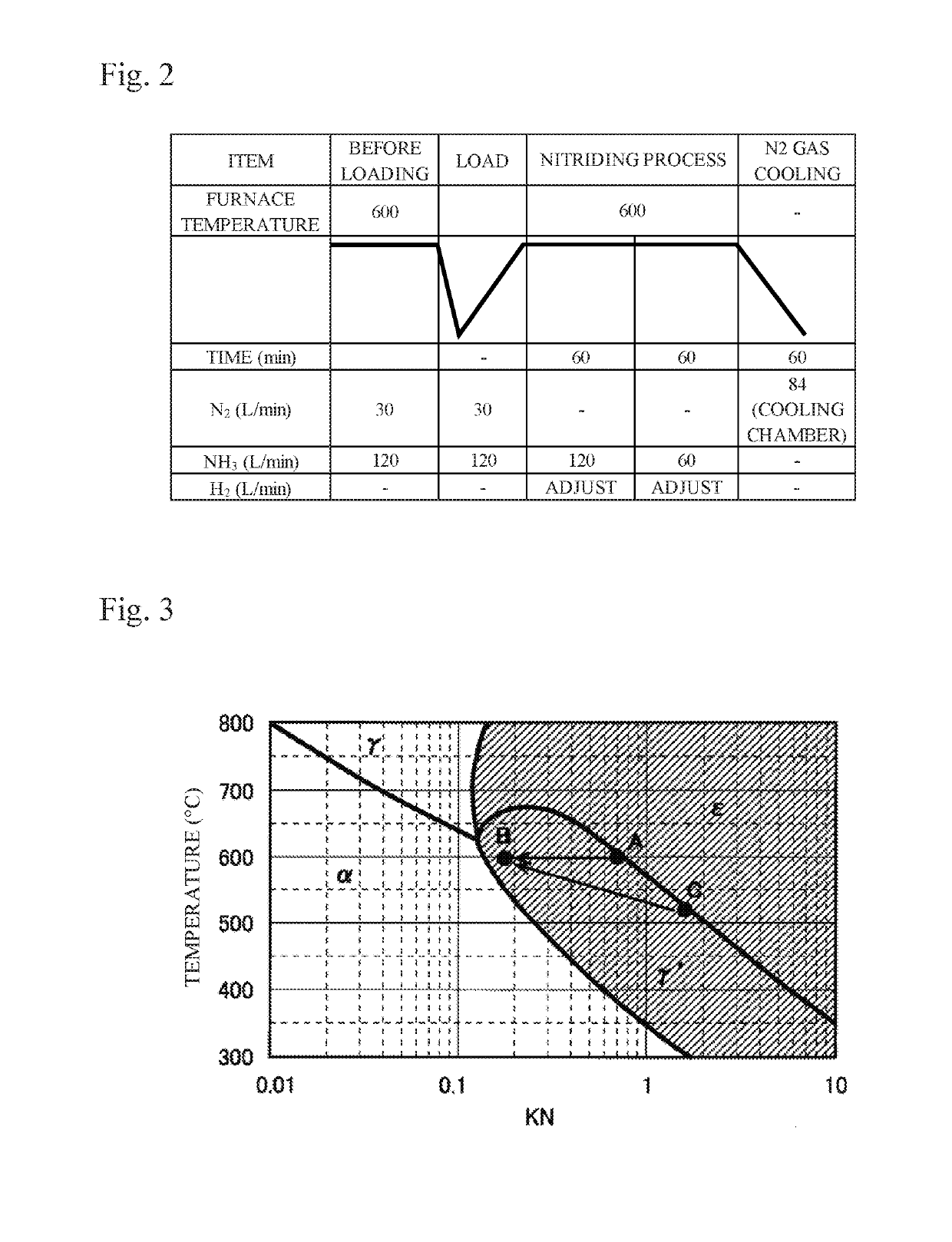
[0038]In an example 1 and a comparative example 1, the ring gears in the cylindrical shape were subjected to the nitriding process. An eight-tier jig was used, the number of the members loaded thereon was 320, and they were loaded in a flat manner. In the example 1, a nitriding process was performed in which the first nitriding process step is performed in an atmosphere of KN=1.03 for ten minutes, and the second nitriding process step was performed in an atmosphere of KN=0.24 for 110 minutes. In the comparative example 1, a nitriding process was performed in an atmosphere of KN=0.25 for 120 minutes. Conditions and results of the nitriding processes are presented in Table 1. Note that a temperature condition was set as indicated in FIG. 2.

[0039]

TABLE 1SOAKING 1NH3H2SOAKING 2NH3H2N2FLOWFLOWNH3PARTI...


PUM

PropertyMeasurementUnit
temperaturesaaaaaaaaaa
flow velocityaaaaaaaaaa

Abstract

A first nitriding process step is performed in which a steel member is subjected to a nitriding process in a nitriding gas atmosphere having a nitriding potential with which a nitride compound layer having a γ′ phase or an ε phase is generated, and thereafter a second nitriding process step is performed in which the steel member is subjected to a nitriding process in a nitriding gas atmosphere having a nitriding potential lower than the nitriding potential in the first nitriding process step, to thereby precipitate the γ′ phase in the nitride compound layer. It is possible to generate the nitride compound layer having a desired phase mode uniformly all over a component to be treated and to manufacture a nitrided steel member high in pitting resistance and bending fatigue strength.

Description

TECHNICAL FIELDCross Reference to Related Application[0001]This application is based upon and claims the benefit of priority from Japanese Patent Application No. 2013-204786 filed on Sep. 30, 2013; the entire contents of which are incorporated herein by reference.[0002]The present invention relates to a nitriding process method of a steel member, the method forming a nitride compound layer on a surface of the steel member by a nitriding processBACKGROUND ART[0003]Steel members such as gears used in automobile transmissions are required to be high in pitting resistance and bending fatigue strength, and to meet such requirement, increasing strength by a carburizing process or a nitriding process has been in practice as a method to strengthen steel members such as gears.[0004]It has been conventionally known that, for improving pitting resistance and bending fatigue strength of a steel member, it is effective to generate an iron nitride compound layer whose main component is a γ′ phase...

Claims


Application Information

Patent Timeline
Patent Type & Authority Patents(United States)
IPC IPC(8): C23C8/26C23C8/80C21D1/06C21D9/32C21D9/00
CPCC23C8/26C21D1/06C23C8/80C21D9/32C21D9/0056
Inventor SHIMIZU, YUICHIROMAEDA, SUSUMUKOBAYASHI, ATSUSHI
Owner DOWA THERMOTECH
Why Eureka
Try Eureka