
Apparatus for a dynamic multi-axis heterodyne interferometric vibrometer

a vibrometer and multi-axis technology, applied in the field of coherent optical vibration sensing, can solve problems such as interference patterns with two carrier frequencies

Inactive Publication Date: 2019-08-20
UNITED STATES OF AMERICA THE AS REPRESENTED BY THE SEC OF THE ARMY
View PDF12 Cites 6 Cited by
  • Summary
  • Abstract
  • Description
  • Claims
  • Application Information

AI Technical Summary

Benefits of technology

The invention is a device that combines three different types of sensors to measure light scattered from a moving surface. It can observe five degrees of freedom, including in-plane translation, out-of-plane rotation, and out-of-plane displacement using a single coherent illumination source. The device uses a special interferometer to collect optical field data and a receive Mach-Zehnder interferometer to produce an interference pattern with two carrier frequencies. The device is capable of measuring changes in the optical field caused by the object's movement, and can be used to create high-speed videos of dynamic objects.

Problems solved by technology

Mixing the reference and measurement fields on a high-speed focal plane array creates an interference pattern with two carrier frequencies.

Method used


Image

  • Apparatus for a dynamic multi-axis heterodyne interferometric vibrometer
  • Apparatus for a dynamic multi-axis heterodyne interferometric vibrometer

Examples


Embodiment Construction

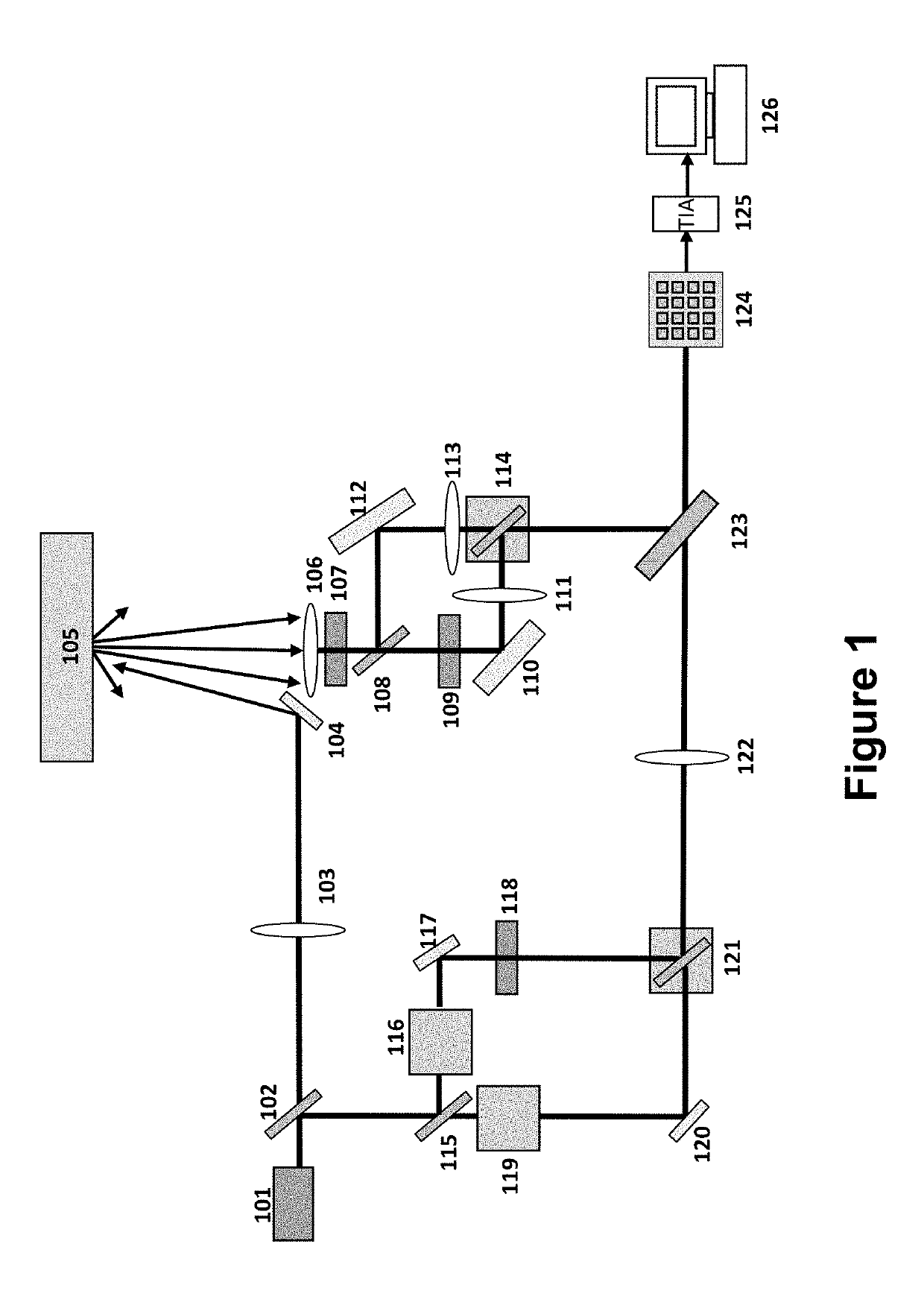
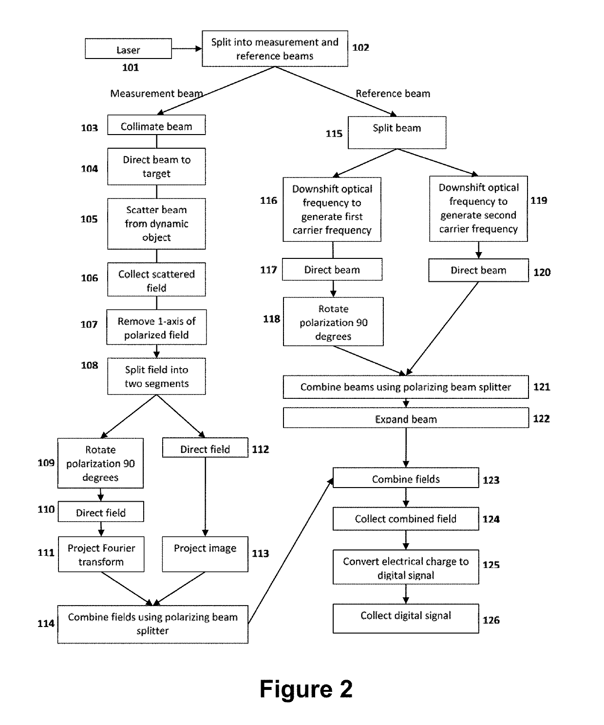
[0010]An exemplary multi-axis heterodyne interferometric vibrometer is represented in FIG. 1, and its exemplary process is shown in FIG. 2. FIG. 1 shows schematic of the multi-axis heterodyne interferometric vibrometer with a dynamic diffuse-scatterer for the target. Specifically, shown in FIG. 1 are: 101, 532 nm laser source; 102, 50:50 beam splitter; 103, beam collimator; 104, mirror; 105, dynamic diffuse scatterer; 106, 100 mm focal length collecting lens; 107, polarizing filter; 108, 50:50 beam splitter; 109, half wave plate; 110, mirror; 111, 125 mm focal length converging lens; 112, mirror; 113, 100 mm focal length converging lens; 114, 50:50 polarizing beam splitter; 115, 50:50 beam splitter; 116, 10 kHz acousto-optic modulator (AOM); 117, mirror; 118, half wave plate; 119, 15 kHz AOM; 120, mirror; 121, 50:50 polarizing beam splitter; 122, −25 mm focal length diverging lens; 123, 70:30 beam splitter; 124, 512×512 pixel focal plane array sampling 40,000 frames per second (FPS)...


PUM


Abstract

A multi-axis heterodyne interferometer is disclosed for observations of five degrees of dynamic freedom using a single illumination source. The sensor utilizes polarization and frequency multiplexing to simultaneously observe and separate the image and Fourier planes following scattering of coherent illumination from a dynamic surface. Multiple carrier frequencies and polarizations separate two segments of a Mach-Zehnder interferometer. Segments of this interferometer have unique optical configurations to generate the image and Fourier planes simultaneously on a focal plane array. The measured irradiance contains information pertaining to an object's in-plane translation, out-of-plane rotation, and out-of-plane displacement.

Description

GOVERNMENT INTEREST[0001]The invention described herein may be manufactured, used, sold, imported, and / or licensed by or for the Government of the United States of America.FIELD OF THE INVENTION[0002]The present invention relates to coherent optical vibration sensing, specifically to measure dynamic multi-axis motion of an object.BACKGROUND OF THE INVENTION[0003]Coherent optical vibration sensors have been investigated for use in numerous applications including strain measurements, equipment diagnostics, medical imaging, and seismic sensing. Various techniques have been utilized to observe surface motion including heterodyne laser Doppler vibrometry (e.g., U.S. Pat. No. 4,834,111 to Khanna et al.) for observation of surface velocity in the axial dimension of the interrogation beam, shearography (e.g., U.S. Pat. No. 5,011,280 to Hung) for observation of the gradient of displacement in two dimensions, electronic speckle pattern interferometry (e.g., U.S. Pat. No. 4,018,531 to Leendert...

Claims


Application Information

Patent Timeline
Patent Type & Authority Patents(United States)
IPC IPC(8): G01B9/02G02B27/10G02B27/30G02B27/28G01H9/00G02B27/09
CPCG01B9/02027G01B9/02003G01B9/02011G02B27/283G02B27/30G01H9/00G02B27/10G02B27/288G01B9/02041G02B27/09G01B2290/60G01B2290/70G01B9/02028G01B9/02043
Inventor PEREA, JAMES D.LIBBEY, BRADLEY W.
Owner UNITED STATES OF AMERICA THE AS REPRESENTED BY THE SEC OF THE ARMY
Learn More