
Pane having an electrical connection element and a flexible connection cable

a flexible connection and connection element technology, applied in the direction of flexible conductors, heater elements, transparent/reflecting heating arrangements, etc., can solve the problems of mechanical strain on the solder connection, reduced service life of lead-free solders, and difficulty in ensuring the safety of the connection element, so as to achieve advantageous stability of the connection element and improve service life. , the effect of high stiffness

Active Publication Date: 2019-08-20
SAINT-GOBAIN GLASS FRANCE
View PDF41 Cites 0 Cited by
  • Summary
  • Abstract
  • Description
  • Claims
  • Application Information

AI Technical Summary

Benefits of technology

The patent text describes a new invention that provides a flexible connection cable with adequate stiffness for easy plugging with one hand. The cable has a coating that improves wetting and adhesion with the soldering compound, while also increasing electrical conductivity. This results in a connection that is both flexible and secure. The invention thus combines the benefits of traditional stiffening elements and heat shrink tubes to provide a flexible cable that can withstand critical shearing and leverage forces.

Problems solved by technology

However, the stiff connection part is associated with the disadvantage that shearing and leverage forces that strain the solder connection between the connection element and the pane can occur at the time the connection cable is plugged on.
The mechanical straining of the solder connection is problematic in particular with lead-free soldering compounds, which will assume increasing significance in the future.
However, lead-free solders typically have significantly less ductility than lead-containing solders and are frequently significantly more brittle.
Consequently, lead-free soldering compounds are incapable of compensating mechanical strains to the same extent.
Shearing and leverage forces are, to be sure, prevented by this; however, the connection cable can be plugged onto the flexible connection cable with one hand only with difficulty or not at all.
This increases the production-technology cycle times and is, consequently, disadvantageous for industrial mass production.

Method used


Image

  • Pane having an electrical connection element and a flexible connection cable
  • Pane having an electrical connection element and a flexible connection cable
  • Pane having an electrical connection element and a flexible connection cable

Examples


Embodiment Construction

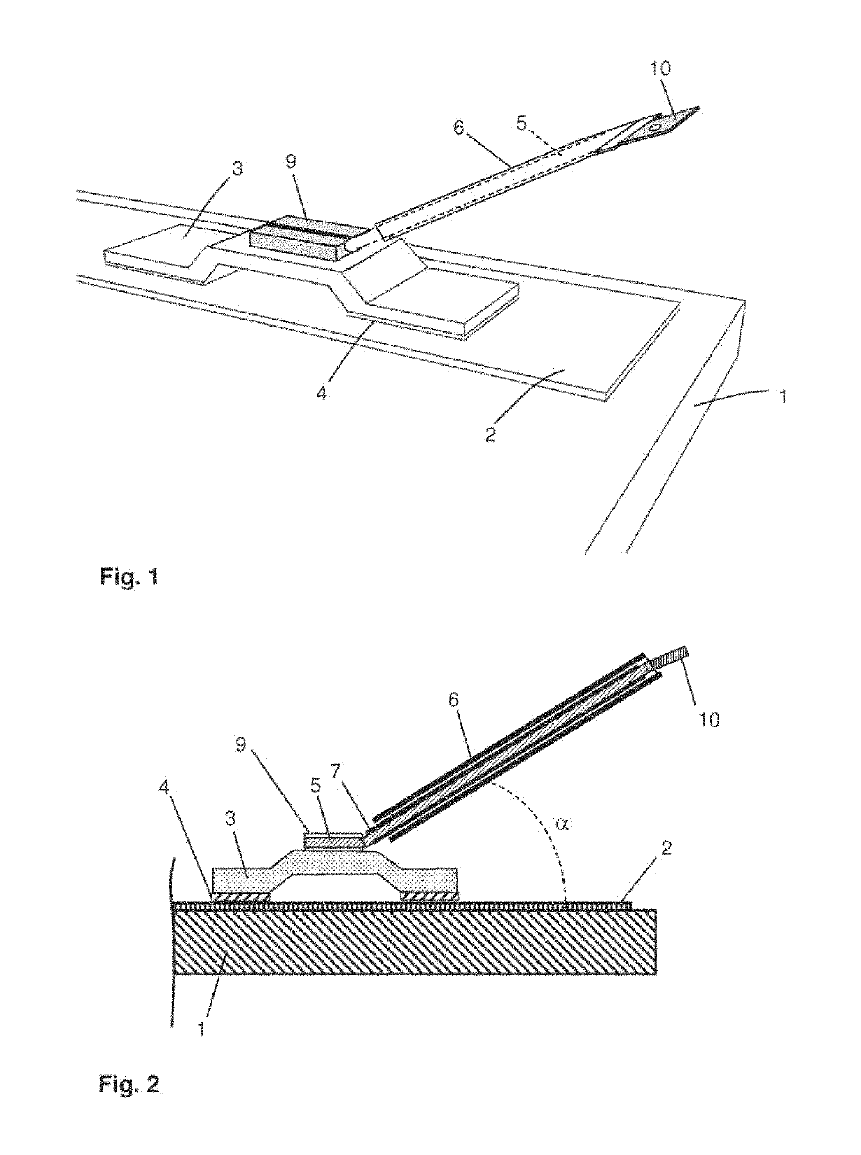
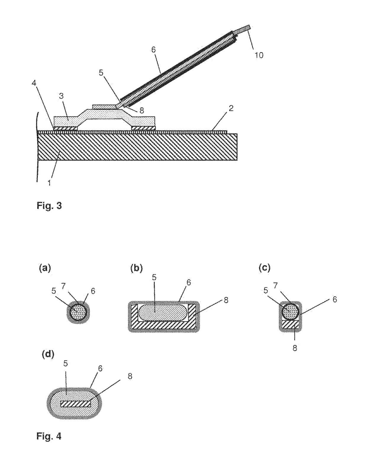
[0090]FIG. 1 and FIG. 2 depict in each case a detail of a pane according to the invention in the region of the electrical connection element 3. The pane comprises a substrate 1, which is a 3-mm-thick thermally prestressed single pane safety glass made of soda lime glass. The substrate 1 has, for example, a width of 150 cm and a height of 80 cm and is intended as a rear window of a passenger car. An electrically conductive structure 2 in the form of a heating conductor structure that contains silver particles and glass frits is printed onto the substrate 1. In the edge region of the pane, the electrically conductive structure 2 is widened to a width of, for example, 10 mm and forms a contact surface for the electrical connection element 3. A masking screenprint (not shown) is also situated in the edge region of the substrate 1.

[0091]The connection element 3 is implemented in the form of a bridge. It comprises two foot regions on whose surfaces facing the substrate 1 the soldering sur...


PUM

PropertyMeasurementUnit
thicknessaaaaaaaaaa
thicknessaaaaaaaaaa
lengthaaaaaaaaaa

Abstract

A pane with at least one electrical connection element is described. The pane having at least a substrate, an electrically conductive structure on a region of the substrate, a connection element that is connected via a soldering compound to a region of the electrically conductive structure, and a flexible connection cable connected to the connection element. The connection cable is provided with a stiffening element and the connection cable with the stiffening element is enshrouded by a heat shrink tube.

Description

CROSS REFERENCE TO RELATED APPLICATIONS[0001]The present application is the U.S. national stage entry of International Patent Application No. PCT / EP2015 / 076186, filed internationally on Nov. 10, 2015, which, in turn, claims priority to European Patent Application No. 14198186.0, filed on Dec. 16, 2014.BACKGROUND OF THE INVENTION[0002]The invention relates to a pane with an electrical connection element and a flexible connection cable, a method for its production, as well as its use.[0003]The invention further relates to a pane with an electrical connection element for vehicles with electrically conductive structures such as, for example, heating conductors or antenna conductors. The electrically conductive structures are customarily provided with soldered-on electrical connection elements that are connected to the vehicle's electrical system via connection cables.[0004]The connection cables to the vehicle's electrical system are typically not connected directly to the connection ele...

Claims


Application Information

Patent Timeline
Patent Type & Authority Patents(United States)
IPC IPC(8): H01R4/02H01B7/04H01B7/18H01B7/40H05B3/84H01B7/02H01R4/18H05B3/06H01R4/72H01R4/58B60R16/02H01R12/62H01B7/08
CPCH01R4/72H01R4/58H05B3/84H01B7/0216H01B7/04H01B7/1895H01B7/40H01R4/029H01R4/187H05B3/06B60R16/02H01B7/08H01R4/183H01R12/62H05B2203/016
Inventor REUL, BERNHARDRATEICZAK, MITJASCHMALBUCH, KLAUS
Owner SAINT-GOBAIN GLASS FRANCE
Learn More