Fan wheel having a rib structure provided on a hub

a technology of ribs and fan wheels, which is applied in the direction of machines/engines, mechanical equipment, liquid fuel engines, etc., can solve the problems of high production costs of this kind of hub structure and strong excitation in the tilting and bending direction of the fan, so as to increase the stiffness and increase the dynamic strength of the fan, and increase the effect of the fan

Active Publication Date: 2019-08-27
MAHLE INT GMBH
View PDF26 Cites 1 Cited by
  • Summary
  • Abstract
  • Description
  • Claims
  • Application Information

AI Technical Summary

Benefits of technology

[0011]In an exemplary embodiment of the invention, the fan wheel for propelling cooling air, in particular for an internal combustion engine, has a hub on which a plurality of fan blades is arranged, whereby the hub has a circumferential rib structure. In a fan wheel, which is designed with a simple structure and nonetheless has a high resistance to tilting and bending of the fan wheel, the rib structure includes substantially rectangular and flat ribs having an edge region and sitting with the edge region thereof sit on the hub and oriented substantially tangentially to the circumferential direction of the hub in their longitudinal extent, the ribs being in contact with one another. As a result, the ribs achieve a predetermined length, so that they run sufficiently close to a center of the fan wheel. This has the advantage that a high resistance, in particular by the long ribs, to deflection of the fan wheel is produced and as a result the dynamic strength of the fan is increased. Because the flat ribs are attached to the flat hub, there is no costly hub structure.
[0014]In an embodiment, the flat rib extends from the first fan blade to the directly adjacent fan blade. To increase further the stiffness and strength of the fan, in an alternative the straight rib can extend from the first fan blade to the next but one fan blade. It is also conceivable, however, that the flat rib extends from one fan blade to the third next fan blade. The dynamic strength of the fan is increased by the crossing of the flat ribs, which start from the different fan blades and lead to the corresponding first, second, or third next fan blade.
[0015]To increase the stiffness of the fan in the area of the attachment points of a coupling, the ribs formed flat or straight in this way run close to the screw points of the coupling, without crossing one another.

Problems solved by technology

A hub structure of this kind is very expensive in terms of production and is not always sufficient to cancel out the vibrations of the internal combustion engine, which cause a strong excitation in the tilting and bending direction of the fan.

Method used


Image

  • Fan wheel having a rib structure provided on a hub
  • Fan wheel having a rib structure provided on a hub
  • Fan wheel having a rib structure provided on a hub

Examples


Embodiment Construction

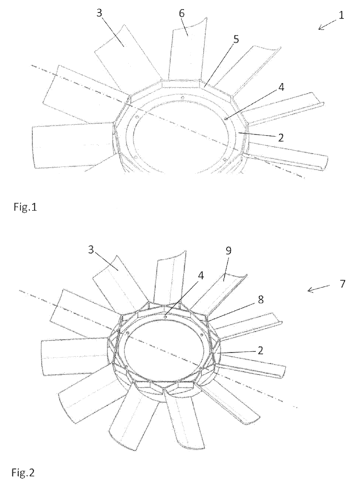
[0024]An exemplary embodiment of fan wheel 1 of the invention, which has a flat, ring-shaped hub 2, on which the plurality of fan blades 3 is arranged, which extend outwardly approximately in a radial direction, is illustrated in FIG. 1. Attachment points 4 for a visco coupling, which is not illustrated further, is shown on the radially inner edge of hub 2; fan wheel 1 can be fastened to the points and fan wheel 1 can be connected via the points to a shaft of an internal combustion engine.

[0025]Different bars 5 are attached to the flat, ring-shaped hub 2; these are made flat and rectangular and lead from one fan blade 3 to the directly following fan blade 6. In this case, bars 5 are in contact at their respective ends in the circumferential direction of hub 2 and do not cross. In this case, a bar 5 begins approximately at the level of one of the edges of a fan blade 3 and ends approximately at the other edge of fan blade 3.

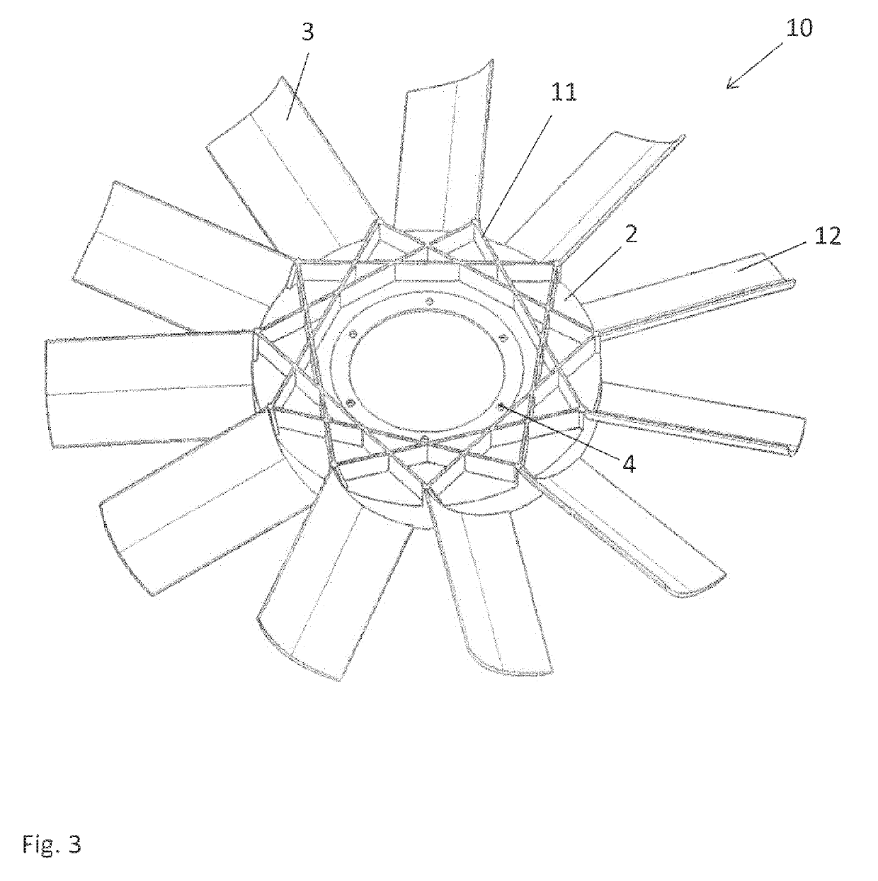
[0026]FIG. 2 shows a fan wheel 7, in which likewise approxim...


PUM


Abstract

A fan wheel for propelling cooling air for an internal combustion engine, including a hub on which a plurality of fan blades is arranged and which includes a rib structure that extends peripherally and has substantially rectangular and flat ribs having an edge region. The ribs sit on the hub by the edge regions thereof and have a longitudinal direction that extends substantially tangentially to the circumferential direction of the hub, the ribs being in contact with one another.

Description

[0001]This nonprovisional application is a continuation of International Application No. PCT / EP2015 / 070629, which was filed on Sep. 9, 2015, and which claims priority to German Patent Application No. 10 2014 219 046.0, which was filed in Germany on Sep. 22, 2014, and which are both herein incorporated by reference.BACKGROUND OF THE INVENTION[0002]Field of the Invention[0003]The invention relates to a fan wheel, in particular for propelling cooling air, in particular for an internal combustion engine, comprising a hub on which a plurality of fan blades is arranged and whereby the hub has a rib structure.[0004]Description of the Background Art[0005]So-called visco fans for engine cooling are fastened by means of a fluid friction coupling, a so-called visco coupling, to the crankshaft of the internal combustion engine and supply the internal combustion engine with air for cooling. Vibrations of the internal combustion engine are therefore transmitted via the coupling to the fan. The fa...

Claims


Application Information

Patent Timeline
Patent Type & Authority Patents(United States)
IPC IPC(8): F04D29/32F04D29/66F04D19/00F01P5/02
CPCF04D19/002F04D29/329F04D29/666F04D29/668F01P5/02
Inventor ASCHERMANN, UWE
Owner MAHLE INT GMBH
Why Eureka
Try Eureka