Time-to-digital converter

a converter and time-to-digital technology, applied in the field of time-to-digital converters, can solve the problems of only weak switching noise in the power supply insensitive etc., and achieve the effects of reducing the impact of oscillator phase noise on the output of the time-to-digital converter, low disturbance of the power supply, and weak switching nois

Active Publication Date: 2019-08-27
DELTA ELECTRONICS INTL SINGAPORE +1
View PDF6 Cites 2 Cited by
  • Summary
  • Abstract
  • Description
  • Claims
  • Application Information

AI Technical Summary

Benefits of technology

[0006]It is an object of the present disclosure to provide a time-to-digital converter with an invertible oscillator. By utilizing two opposite oscillation directions of the same invertible oscillator, the impact of the oscillator phase noise to the output of the time-to-digital converter is reduced. In addition, the output of the time-to-digital converter is insensitive to the interference from the power supply since the impact of the power noise is partly cancelled out. Besides, the time-to-digital converter introdu...

Problems solved by technology

In addition, the output of the time-to-digital converter is insensitive to the interference from the power supply since the impact of the power noise is partly cancelled out.
Besides, the ...

Method used


Image

  • Time-to-digital converter
  • Time-to-digital converter
  • Time-to-digital converter

Examples


Embodiment Construction

[0015]The present disclosure will now be described more specifically with reference to the following embodiments. It is to be noted that the following descriptions of preferred embodiments of this disclosure are presented herein for purpose of illustration and description only. It is not intended to be exhaustive or to be limited to the precise form disclosed.

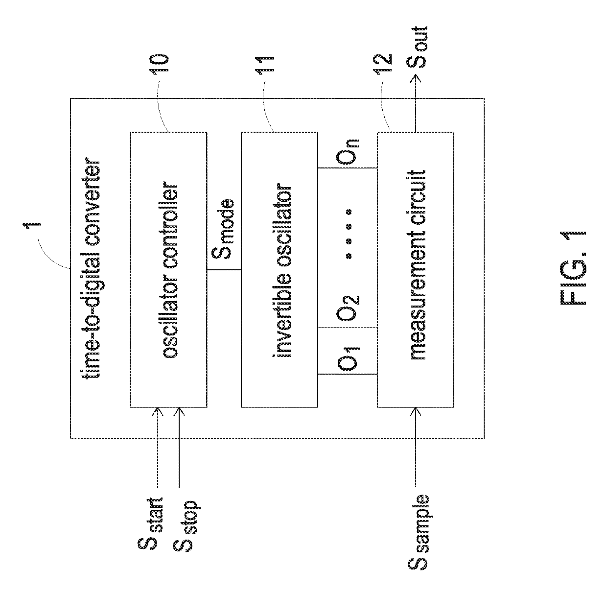
[0016]FIG. 1 is a block diagram illustrating a time-to-digital converter according to an embodiment of the present disclosure. As shown in FIG. 1, the time-to-digital converter 1 includes an oscillator controller 10, an invertible oscillator 11 and a measurement circuit 12.

[0017]The oscillator controller 10 receives a start signal Sstart and a stop signal Sstop, and outputs a mode signal Smode according to the start signal Sstart and the stop signal Sstop. In an embodiment, preferably but not exclusively, the level of the mode signal Smode is changed while the start signal Sstart or the stop signal Sstop is at the rising edge.

[...


PUM


Abstract

A time-to-digital converter is provided. The time-to-digital converter comprises an oscillator controller, an invertible oscillator and a measurement circuit. The oscillator controller receives a start signal and a stop signal and outputs a mode signal. The invertible oscillator is electrically connected with the oscillator controller for receiving the mode signal. The oscillation direction of the invertible oscillator is inverted according to the mode signal, and the invertible oscillator outputs plural delay signals. The measurement circuit is electrically connected with the invertible oscillator for receiving the plural delay signals. The measurement circuit receives a sampling signal, samples the plural delay signals in accordance with the sampling signal, and outputs an output signal.

Description

CROSS-REFERENCE TO RELATED APPLICATION[0001]This application claims priority to Singapore Patent Application No. 10201802514R, filed on Mar. 27, 2018. The entire content of the above-mentioned patent application is incorporated herein by reference for all purposes.FIELD OF THE DISCLOSURE[0002]The present disclosure relates to a time-to-digital converter, and more particularly to a time-to-digital converter having an oscillator with invertible oscillation direction.BACKGROUND OF THE DISCLOSURE[0003]Time domain and digital domain have been regarded as the reliable representations for analog information processing in finer scale geometries. A time-to-digital converter is commonly used in a processing system circuit to convert the time information into the digital representation. The time-to-digital converter is widely applied in thriving areas including digital phase-locked loops (DPLL) for radio frequency (RF) wireless communication systems, the time-based analog-to-digital converter ...

Claims


Application Information

Patent Timeline
IPC IPC(8): G04F10/00H03M1/08
CPCH03M1/50G04F10/005H03M1/0854H03M1/0836
Inventor LIANG, ZHIPENGBOON, CHIRN CHYEYI, XIANGKEE, JACK SHENG
Owner DELTA ELECTRONICS INTL SINGAPORE
Why Eureka
Try Eureka