Power line resistance sensing device
- Summary
- Abstract
- Description
- Claims
- Application Information
AI Technical Summary
Benefits of technology
Problems solved by technology
Method used
Image
Examples
first embodiment
[0054]FIG. 5 shows a detailed circuit diagram of the lamp system 1 according to the first embodiment of the present invention.
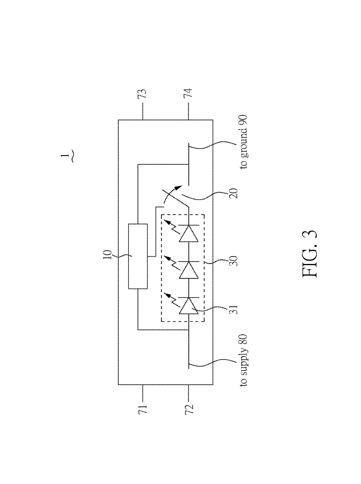
[0055]The lamp system 1 includes a power line resistance sensing device 10, an LED switch 20, a testing switch 21, an LED module 30, a testing current source 40, and a power supply 70.
[0056]The LED module 30 is connected to the power supply 70 between power lines (a supply line 80 and a ground line 90) through the LED switch 20. The LED module 30 includes a plurality of LEDs 31 for lighting.
[0057]The power line resistance sensing device 10 includes a control unit 50, a first resistor R1, a second resistor R2, and a first capacitor C1. The control unit 50 has three pins: dry (first pin), Idrv (second pin), and ref (third pin). The pin dry is connected to and controls the LED switch 20 to turn on / off the LED module 30. The pin Idrv is connected to and controls the testing switch 21 to fire (inject) a testing current dI from the testing current source 40. The pi...
second embodiment
[0078]FIG. 7 shows a detailed circuit diagram of the lamp system 1 according to another embodiment of the present invention.
[0079]The lamp system 1 includes a power line resistance sensing device 10, an LED switch 20, a testing switch 21, an LED module 30, a testing current source 40, and a power supply 70.
[0080]The LED module 30 is connected to the power supply 70 between power lines (a supply line 80 and a ground line 90) through the LED switch 20. The LED module 30 includes a plurality of LEDs 31 for lighting.
[0081]The power line resistance sensing device 10 includes a control unit 60, a first resistor R1, a second resistor R2, and a first capacitor C1. The control unit 50 has four pins: dry (first pin), Idrv (second pin), ref (third pin), and sen (fourth pin). The pin dry is connected to and controls the LED switch 20 to turn on / off the LED module 30. The pin Idrv is connected to and controls the testing switch 21 to fire (inject) a testing current dI from the testing current so...
PUM
 Abstract
Description
Claims
Application Information
 - R&D
- Intellectual Property
- Life Sciences
- Materials
- Tech Scout
- Unparalleled Data Quality
- Higher Quality Content
- 60% Fewer Hallucinations
Browse by: Latest US Patents, China's latest patents, Technical Efficacy Thesaurus, Application Domain, Technology Topic, Popular Technical Reports.
© 2025 PatSnap. All rights reserved.Legal|Privacy policy|Modern Slavery Act Transparency Statement|Sitemap|About US| Contact US: help@patsnap.com


