
Electricity management device, electricity management method, and electricity distribution system inside a house with electricity generating device, utility grid connection, and electric vehicle containing a rechargeable battery in a vehicle-to-grid connection with counter device

a technology of electricity management and counter device, which is applied in the integration of power network operation system, greenhouse gas reduction, transportation and packaging, etc., can solve the problems of installing an expensive rechargeable battery and solar cells not always generating enough electricity, and achieve the effect of reducing the counter valu

Active Publication Date: 2019-09-10
PANASONIC INTELLECTUAL PROPERTY MANAGEMENT CO LTD
View PDF151 Cites 7 Cited by
  • Summary
  • Abstract
  • Description
  • Claims
  • Application Information

AI Technical Summary

Benefits of technology

The present invention relates to an electricity management device and method for vehicles that use a rechargeable battery. The device includes a charging electricity accumulator that increases a counter value when the rechargeable battery is charged from grid power and retains the counter value when the battery is recharged from electricity generated by a house generator. The device also includes a discharging electricity accumulator that reduces the counter value as the battery discharges electricity into the house. The technical effects of this invention include efficient management of electricity usage and reduction of energy waste.

Problems solved by technology

However, the solar cells are not always generating enough electricity when the electric vehicle is connected to a charger.
However, in the method of providing a rechargeable battery for the house side as described in Patent Literature 1, it is necessary to install an expensive rechargeable battery in addition to that in the electric vehicle.

Method used


Image

  • Electricity management device, electricity management method, and electricity distribution system inside a house with electricity generating device, utility grid connection, and electric vehicle containing a rechargeable battery in a vehicle-to-grid connection with counter device
  • Electricity management device, electricity management method, and electricity distribution system inside a house with electricity generating device, utility grid connection, and electric vehicle containing a rechargeable battery in a vehicle-to-grid connection with counter device
  • Electricity management device, electricity management method, and electricity distribution system inside a house with electricity generating device, utility grid connection, and electric vehicle containing a rechargeable battery in a vehicle-to-grid connection with counter device

Examples


Embodiment Construction

[0035]Hereinafter, a description is given of an embodiment of the present invention with reference to the drawings.

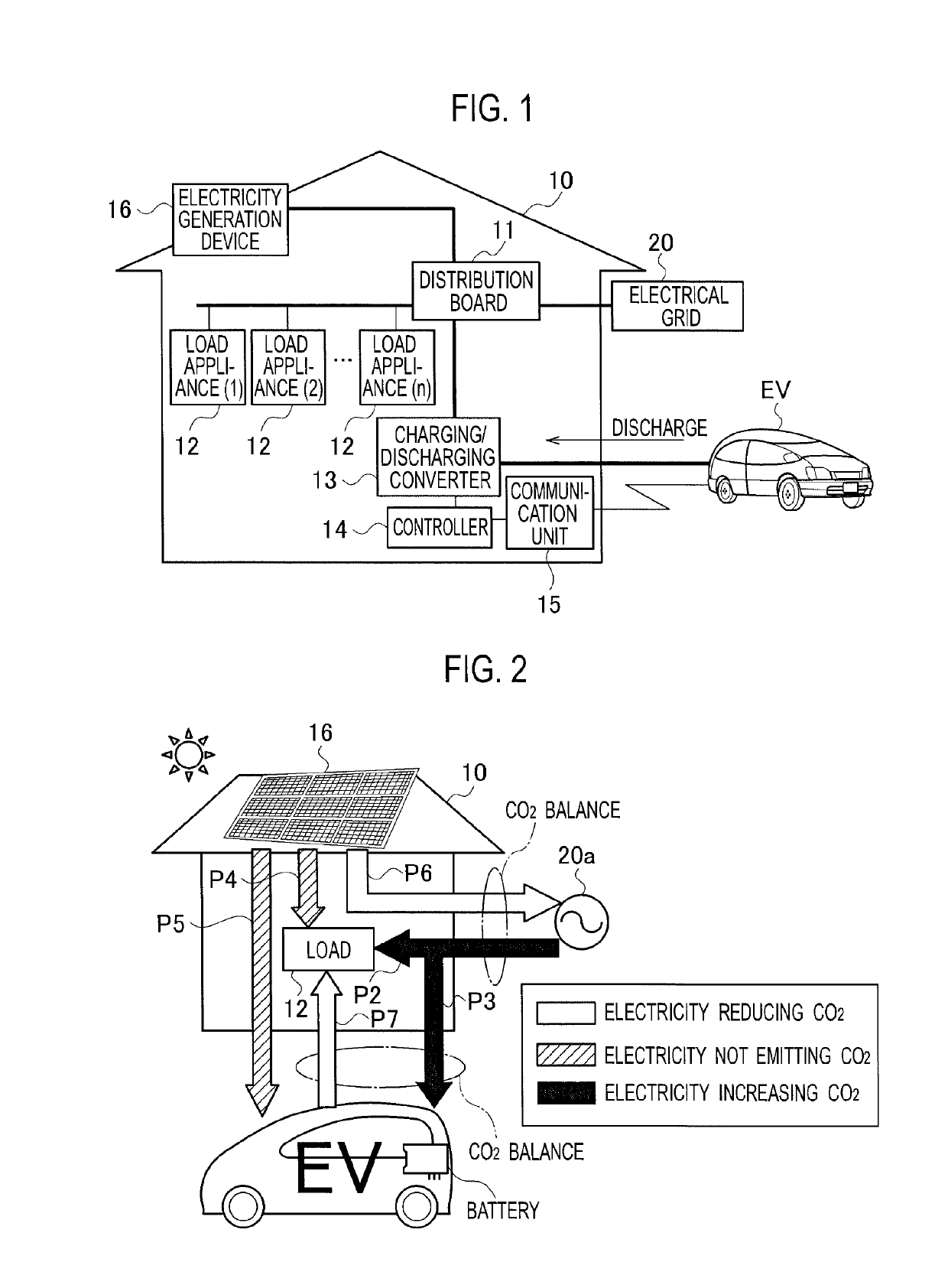
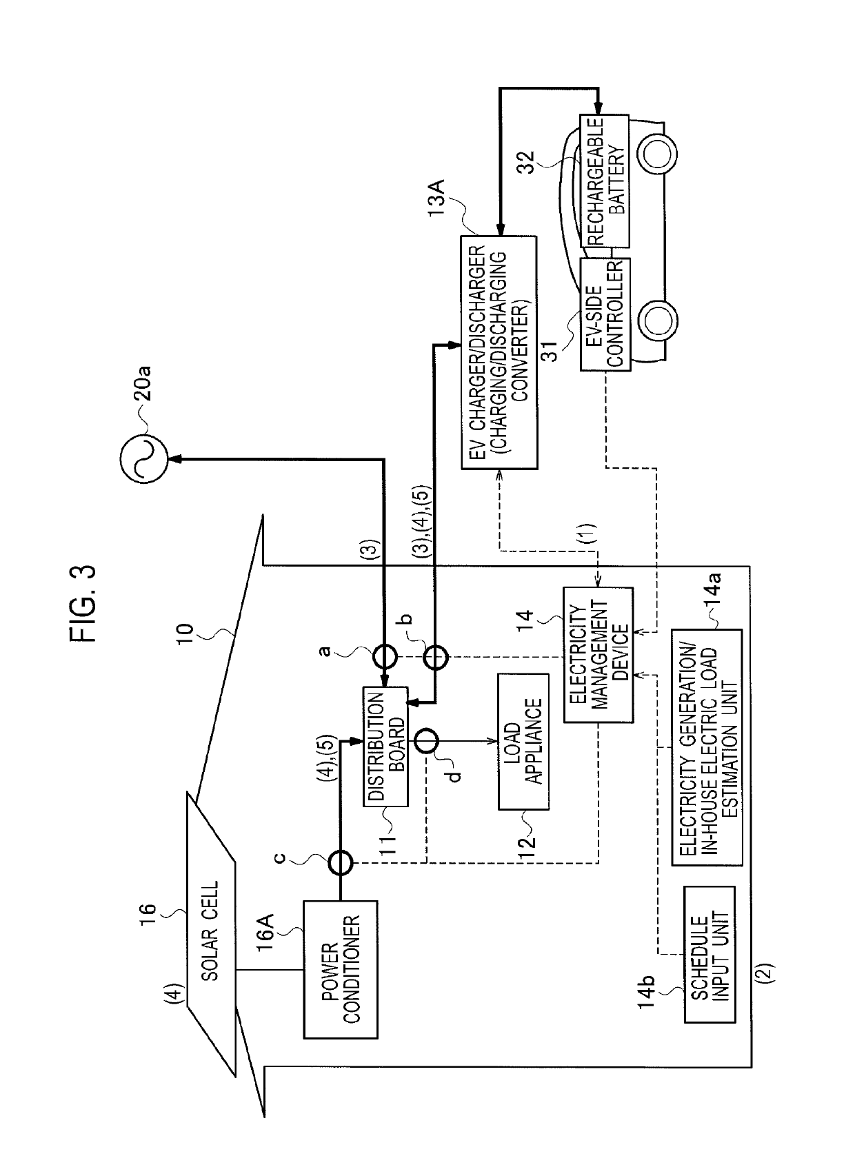
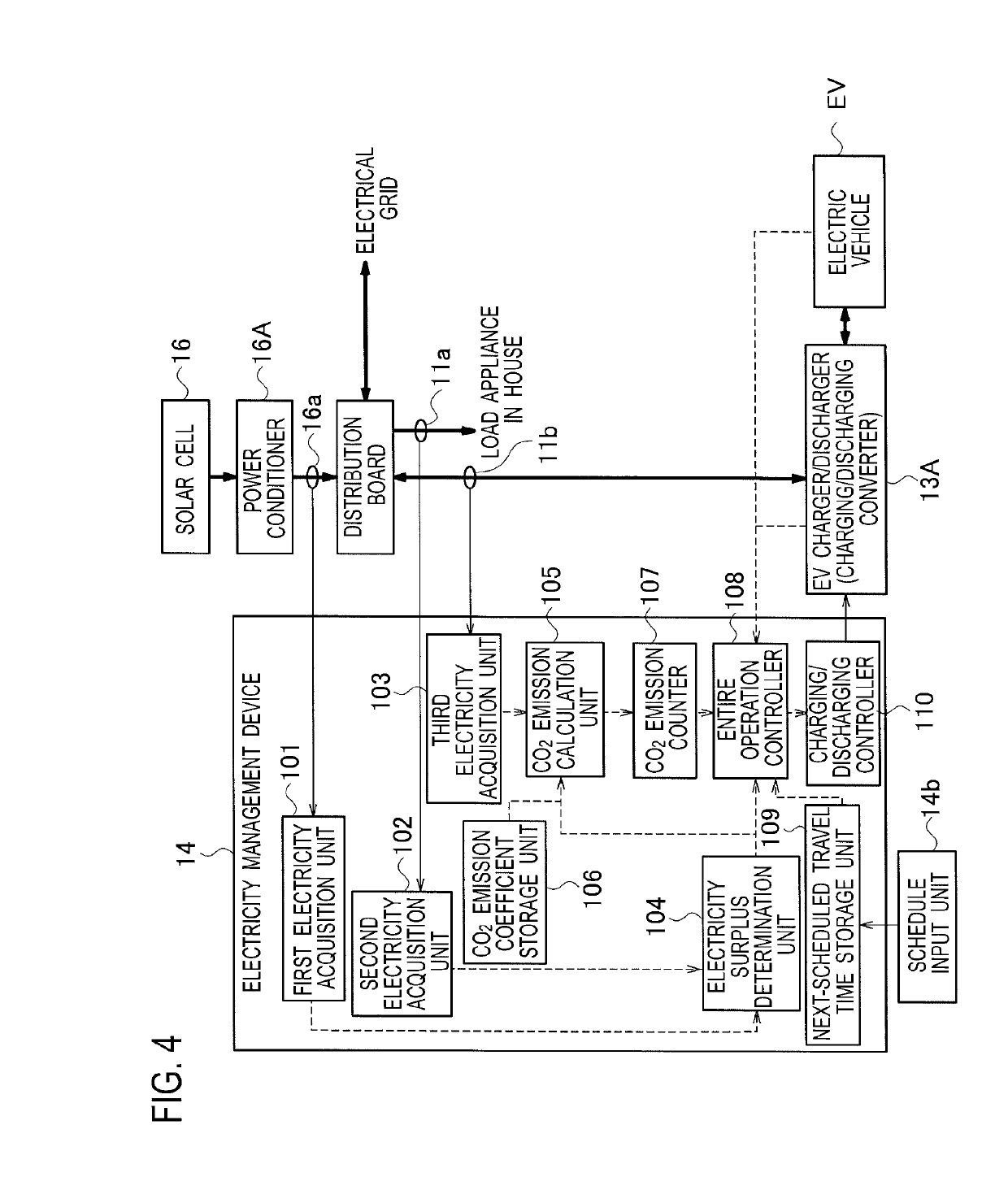
[0036]An electricity distribution system shown as an embodiment of the present invention is configured as illustrated in FIG. 1, for example. This electricity distribution system is focused on the fact that an electric vehicle EV does not emit carbon dioxide (CO2) when traveling but actually emits CO2 when being charged by a grid power supply. The electricity distribution system performs charging from solar cells in preference to charging from the grid power supply, which is used to make up the shortage. After charging the electric vehicle EV from the grid power supply, the electricity distribution system then discharges the electricity supplied from the solar cells to the house. The electricity distribution system thus substantially controls the balance of CO2 emissions to zero (+ / −0).

[0037]In this electricity distribution system, a house 10 connected to an electrical ...


PUM


Abstract

A electricity management device increases a counter value as an electric vehicle is charged from grid power that is supplied from an electrical grid, retains the counter value when the electric vehicle is charged from electricity generated by an electricity generation device, and reduces the counter value as electricity in the electric vehicle is discharged to a distribution board.

Description

RELATED APPLICATIONS[0001]This application is the U.S. National Phase under 35 U.S.C. § 371 of International Application No. PCT / JP2012 / 007413, filed on Nov. 19, 2012, which in turn claims the benefit of Japanese Application No. 2011-254883 filed on Nov. 22, 2011, the disclosures of which Applications are incorporated by reference herein.TECHNICAL FIELD[0002]The present invention relates to an electricity management device, an electricity management program, and an electricity distribution system which manage electricity used in a house and an electric vehicle.BACKGROUND ART[0003]One of known home systems provided with solar cells is an invention described in Patent Literature 1, for example. Patent Literature 1 describes about the following operation. The home system calculates an amount of photovoltaic electricity predicted and an amount of charging electricity predicted for a vehicle rechargeable battery and supplies the photovoltaic electricity to the vehicle rechargeable batter...

Claims


Application Information

Patent Timeline
Patent Type & Authority Patents(United States)
IPC IPC(8): B60L53/30B60L55/00H02J3/38H02J3/32H02J3/00
CPCB60L53/30B60L55/00H02J3/32H02J3/383Y04S10/126Y02E10/563Y02E10/566Y02E60/721Y02E70/30H02J2003/007H02J2203/20H02J2310/48H02J2300/24H02J3/381B60L53/305Y02B10/10Y02E10/56Y02E60/00Y02T90/16Y02T10/70Y02T10/7072Y02T90/12Y04S40/20Y04S20/222Y04S20/242Y02B70/30Y02B70/3225H02J3/322Y04S30/12Y02T90/167H02J2300/20H02J2310/14H02J2310/12H02J3/38
Inventor BABA, AKIRA
Owner PANASONIC INTELLECTUAL PROPERTY MANAGEMENT CO LTD
Learn More