Grinding pad apparatus

a technology of floor grinding and pad, which is applied in the direction of grinding heads, flexible wheel wheels, manufacturing tools, etc., can solve the problems of uneven grinding, inconsistent polishing or grinding, and adding extra grinding time, so as to improve grinding performance and ensure the attachment of components. , the effect of greater and more even floor conta

Active Publication Date: 2019-09-17
HUSQVARNA AB
View PDF108 Cites 1 Cited by
  • Summary
  • Abstract
  • Description
  • Claims
  • Application Information

AI Technical Summary

Benefits of technology

[0003]Notwithstanding, improved floor grinding performance is desired. Furthermore, some of these prior constructions exhibit uneven wear in use which prematurely destroy the pads or cause inconsistent polishing or grinding. Moreover, floor unevenness and cracks may create only partial contact with abrasive grinding members, thereby adding extra grinding time and causing uneven grinding with some prior rigid devices.
[0005]The present pad assembly is advantageous over traditional devices. For example, the flexible metallic reinforcement layer or ring of the present pad apparatus advantageously allows greater and more even floor contact over worn areas and cracks due to disk-to-disk flexibility, which is expected to improve grinding performance. Furthermore, the disk post and method of manufacturing the apparatus advantageously provide a more secure attachment of components. The flexible metallic reinforcement ring, in combination with sintered powdered metal and diamond disks, provide enhanced durability during the grinding operation which is a much harsher, jarring and vibration-prone operating condition than for polishing or honing. Additional advantages and features of the present invention will be readily understood from the following description, claims and appended drawings.

Problems solved by technology

Furthermore, some of these prior constructions exhibit uneven wear in use which prematurely destroy the pads or cause inconsistent polishing or grinding.
Moreover, floor unevenness and cracks may create only partial contact with abrasive grinding members, thereby adding extra grinding time and causing uneven grinding with some prior rigid devices.

Method used


Image

  • Grinding pad apparatus
  • Grinding pad apparatus
  • Grinding pad apparatus

Examples


Embodiment Construction

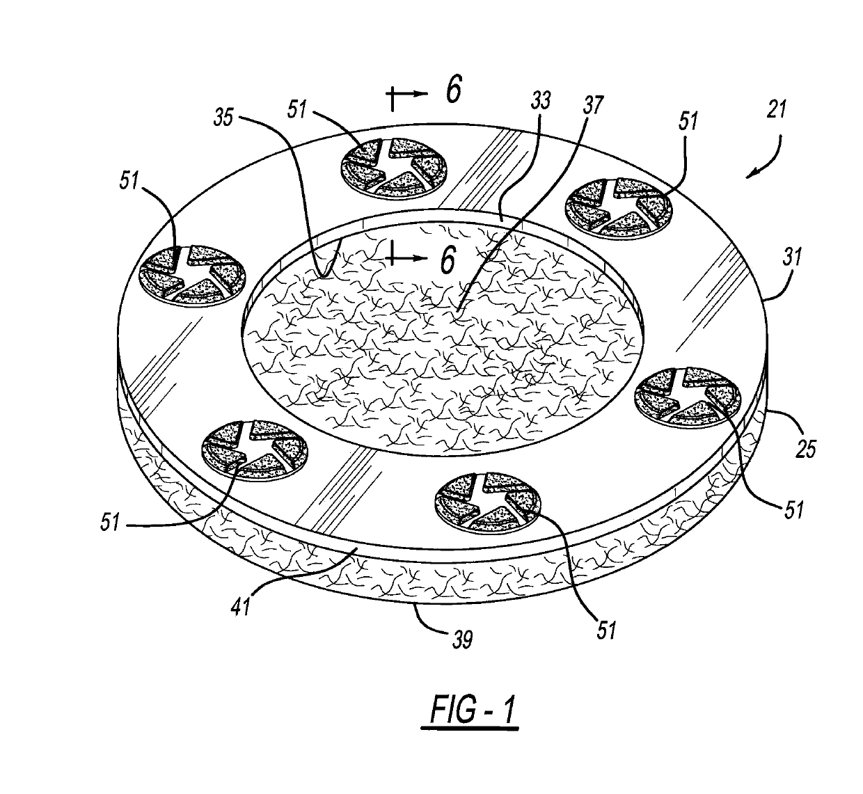
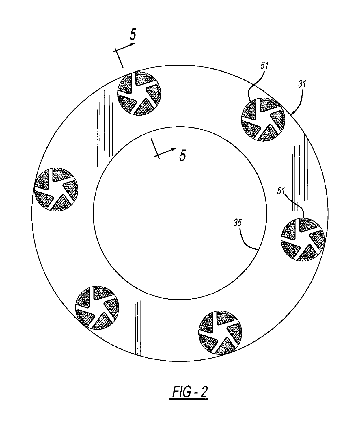
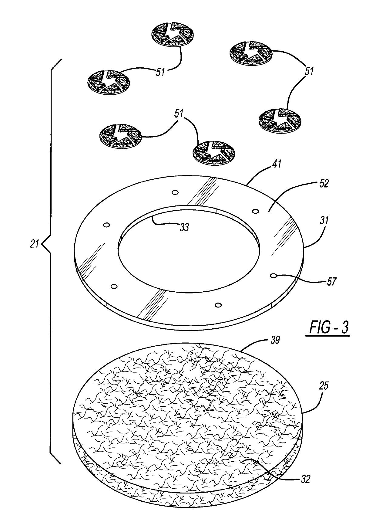
[0013]A preferred embodiment of a grinding pad apparatus 21 is shown in FIGS. 1-6. Pad apparatus 21 is used for grinding composite surfaces, such as concrete, stone or terrazzo floors 23. Grinding pad apparatus 21 includes a base pad 25, which is a flexible and deformable material, including natural and / or artificial fibers mixed with a polymeric resin. However, to save expense, base pad 25 preferably does not employ any diamond particles. Base pad 25 has a generally circular periphery, with a diameter of at least 7 inches, more preferably 7-27 inches, and most preferably 14 inches, and a thickness of at least 0.25 inches and more preferably 0.5-2.0 inches. Of course, base pad 25 could be made in other sizes.

[0014]A reinforcement ring or layer 31 is secured to a bottom face or surface 32 of base pad 25, by a contact cement type of adhesive. Reinforcement ring 31 is generally annular having a central opening 33 with an inner diameter of approximately 9.5 inches and an outer diameter ...


PUM


Abstract

A workpiece abrading pad apparatus is provided. In one aspect, a grinding pad apparatus employs a flexible pad, a flexible metallic reinforcement layer or ring, and multiple floor-grinding disks. In another aspect, a metallic reinforcement ring includes a central hole through which a fiber or foam pad is accessible. Another aspect employs a spring steel reinforcement ring to which multiple diamond-based abrasive disks or dots are attached. In yet another aspect, at least one floor-contacting disk attached to a reinforcement ring includes sintered powdered metal with diamond particles mixed therein. A further aspect employs abrasive, floor-contacting disks or dots including posts extending from backsides thereof for attachment to a reinforcing ring or layer.

Description

BACKGROUND AND SUMMARY[0001]The disclosure relates generally to a pad assembly and more particularly to a floor grinding pad apparatus.[0002]It is known to use fibrous pads for polishing and grinding floors within industrial or commercial buildings. Such polishing or grinding pads are ideally suited for use on concrete, terrazzo, and natural (e.g., marble), engineered and composite stone floors. Examples of such pads and the powered machines used to rotate such can be found in the following U.S. patents and patent publication numbers: 2011 / 0300784 entitled “Flexible and Interchangeable Multi-Head Floor Polishing Disk Assembly” which was invented by Tchakarov et al. and published on Dec. 8, 2011; U.S. Pat. No. 9,174,326 entitled “Arrangement For Floor Grinding” which issued to Ahonen on Nov. 3, 2015; U.S. Pat. No. 6,234,886 entitled “Multiple Abrasive Assembly and Method” which issued to Rivard et al. on May 22, 2001; U.S. Pat. No. 5,605,493 entitled “Stone Polishing Apparatus and Me...

Claims


Application Information

Patent Timeline
Patent Type & Authority Patents(United States)
IPC IPC(8): B24B41/047B24D7/06B24B7/22B24B7/18B24D7/08B24D13/14
CPCB24B41/047B24B7/18B24B7/22B24D13/14B24D7/08B24B7/186B24D7/06
Inventor TCHAKAROV, TCHAVDAR V.
Owner HUSQVARNA AB
Why Eureka
Try Eureka