Voltage based method for fault identification in a transmission line apparatus thereof

a transmission line and fault identification technology, applied in the field of power transmission, can solve problems such as system stability threats, device insulation damage, and device failures, and achieve the effect of high resistance and high accuracy

Active Publication Date: 2019-09-17
HITACHI ENERGY LTD
View PDF20 Cites 2 Cited by
  • Summary
  • Abstract
  • Description
  • Claims
  • Application Information

AI Technical Summary

Benefits of technology

[0048]An embodiment of the present invention provides a method for fault identification in a transmission line and apparatus thereof, which reliably distinguish a temporary fault (i.e. a transient fault) from a permanent fault in the case of a single-phase fault. Such method and apparatus for fault identification can be extensively adopted under all kinds of operation conditions with high accuracy, especially the extreme fault conditions such as a fault with high resistance or heavy load and so on. Consequently such method and apparatus of the present invention can avoid the reclosing of a circuit breaker when the fault is a permanent fault.

Problems solved by technology

However, if a transmission line with a permanent fault is auto-reclosed, some risks may be arisen, for example the primary devices may be damaged, device insulation can be destroyed, the system stability may be threatened, and no continuous current can be supplied stably.
According to the prior arts about the reclosing technique, existed solutions including above mentioned method generally represents good performance in distinguishing a permanent fault from a transient fault in the majority of operational conditions, but for some special conditions such as: the fault in a short transmission line, the fault with high fault resistance or the fault with heavy load, its performance will be degraded and the fault identification will be inaccurate even wrong.
That means such drawback decreases the reliability of adaptive re-closure technique, and customers cannot be thoroughly convinced of utilizing this adaptive re-closure strategy to reclosing the CBs safely.

Method used


Image

  • Voltage based method for fault identification in a transmission line apparatus thereof
  • Voltage based method for fault identification in a transmission line apparatus thereof
  • Voltage based method for fault identification in a transmission line apparatus thereof

Examples


Embodiment Construction

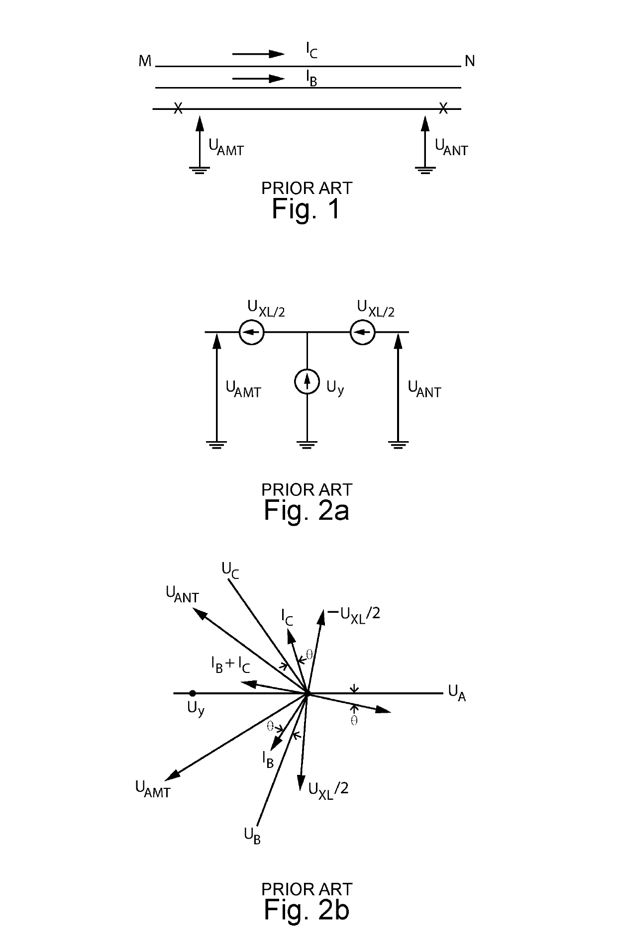
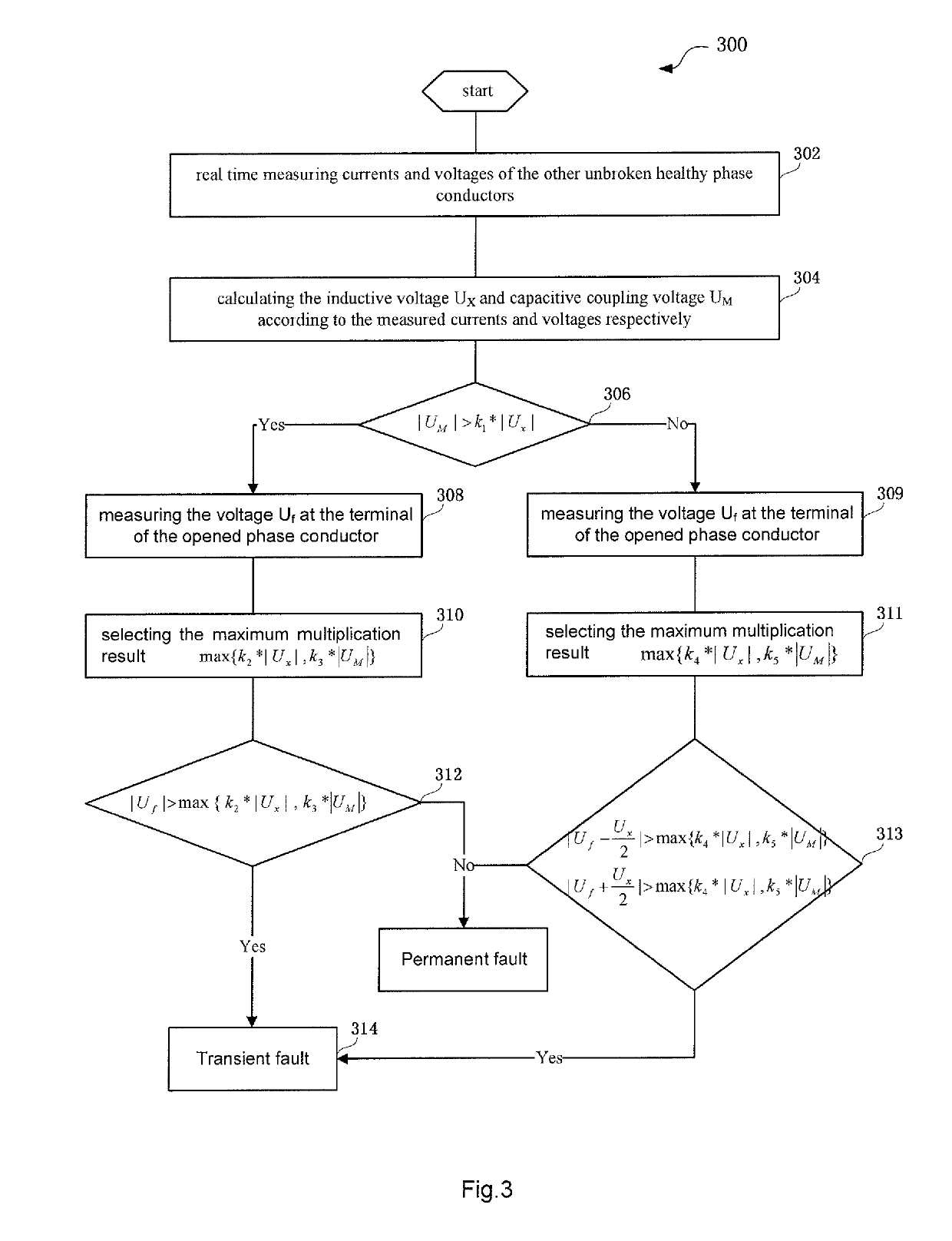
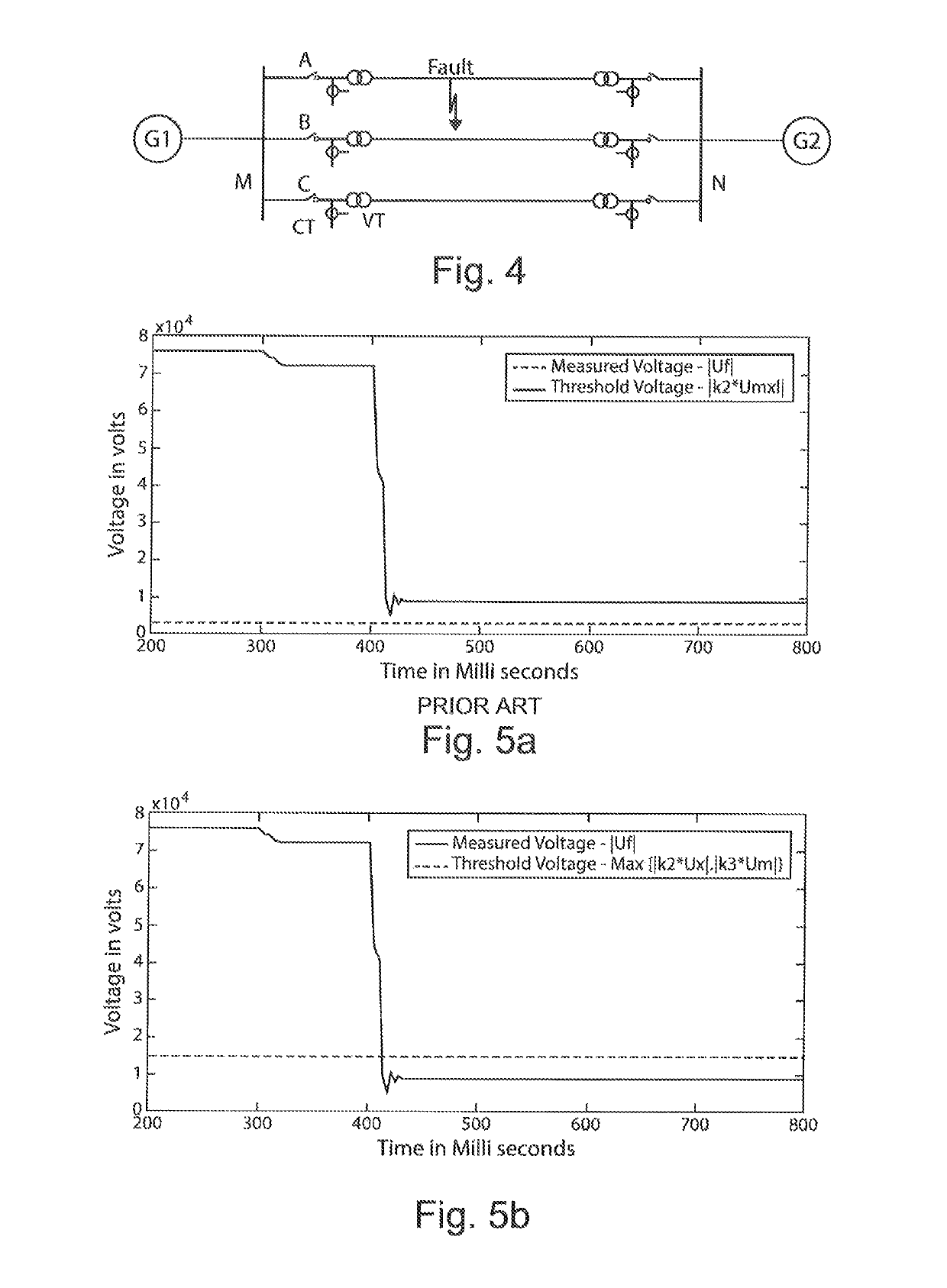
[0057]Exemplary embodiments of the present invention are described in conjunction with the accompanying drawings hereinafter. For the sake of clarity and conciseness, not all the features of actual implementations are described in the specification.

[0058]The method of the present invention aims to reliably distinguish a temporary fault (i.e. a transient fault) from a permanent fault in the case of a single-phase fault, especially under all kinds of operation conditions with high accuracy such as a fault with high resistance or heavy load and so on. Furthermore such method and apparatus of the present invention can avoid the reclosing of a circuit breaker when the fault is a permanent fault. The following embodiments will be illustrated in the case of phase A fault, it will be appreciated to the skilled person that the present invention can be modified to identify the fault types (distinguishing the permanent fault from the transient fault) in the case of phase B fault or phase C fau...


PUM


Abstract

The present invention provides a method for current for fault identification in a transmission line and an apparatus thereof. The method comprises the following steps: measuring the real-time values of the currents and the voltages of the other unbroken healthy phase conductors when a single-phase fault occurs; calculating the inductive voltage and the capacitive coupling voltage according to the measured currents and voltages respectively; comparing the capacitive coupling voltage with the inductive voltage multiplied by a factor, in which the multiplication result is used as a self-adjusted threshold based on the real time load condition of the transmission line; and identifying the fault type based on the maximum of the capacitive coupling voltage and the multiplication.

Description

RELATED APPLICATION[0001]This application is a national filing of PCT application Serial No. PCT / CN2011 / 071887, filed Mar. 17, 2011.FIELD OF THE INVENTION[0002]The invention relates to the field of power transmission, and more particularly to a voltage based method for fault identification in a transmission line and apparatus thereof when the transmission line occurs a single-phase fault.BACKGROUND OF THE INVENTION[0003]For a transmission line, there generally exist two types of faults, i.e. a permanent fault and a temporary fault, in which about 90% of the faults are single-phase faults, and over 80% of the single-phase faults are temporary faults. Auto-reclosing the circuit breaker (CB) is a generally effective way to improve the stability and continuity of a power system. However, if a transmission line with a permanent fault is auto-reclosed, some risks may be arisen, for example the primary devices may be damaged, device insulation can be destroyed, the system stability may be ...

Claims


Application Information

Patent Timeline
Patent Type & Authority Patents(United States)
IPC IPC(8): G01R31/00G01R27/00H02H3/06H02H7/26G01R31/08G01R31/02H02H3/08H02H3/40G01D21/00G06F17/40G01R31/58
CPCG01R31/025H02H3/405H02H3/402H02H7/26H02H3/06G01R27/00G01R31/08G01R31/021H02H3/083G06F17/40G01D21/00G01R31/58G16Z99/00
Inventor YANG, YINGLI, YOUYIPRADEEP, G.
Owner HITACHI ENERGY LTD
Why Eureka
Try Eureka