MIMO radar measurement sensor

a radar and sensor technology, applied in the direction of measuring devices, instruments, using reradiation, etc., can solve the problem that the velocity cannot be exactly calculated, and the speed cannot be only estimated

Active Publication Date: 2019-09-17
ROBERT BOSCH GMBH
View PDF23 Cites 6 Cited by
  • Summary
  • Abstract
  • Description
  • Claims
  • Application Information

AI Technical Summary

Benefits of technology

[0024]This allows an unambiguous estimate of the relative velocity within a velocity measuring range that can be, for example, at least a multiple of the unambiguity range of a measurement with only one of the sequences of ramps. It is advantageous in particular that relatively long time intervals are possible between the ramps, i.e., between the ramp center points, of a sequence, so that the hardware outlay is decreased or a more accurate localization is enabled for the same hardware outlay.
[0025]The particular advantage resulting from the temporal interleaving of the sequences which is thereby simplified is that the baseband signals or spectra thereof that are used for angle determination, which are obtained with different transmission switching states, are measured almost simultaneously, so that phase shifts resulting from relative motions can be minimized and / or can be corrected particularly accurately.
[0026]An improved angle estimate can thus be enabled despite decreased hardware costs due to shorter time intervals.
[0035]Preferably, successive ramps within a respective sequence have an identical ramp slope and an identical difference between their ramp center frequencies as well as, particularly preferably, an identical frequency swing, the aforesaid difference in the ramp center frequencies optionally being not equal to zero, and ramps that have the same ramp index in the respective sequences exhibiting the same ramp slope and the same ramp center frequency as well as, particularly preferably, an identical frequency swing. The phase relationships resulting from the relative velocity of a radar target can be measured particularly accurately, and angle determination is simplified, if the frequency profile of all ramps of all sequences is identical, except for the frequency difference from ramp to ramp which is optionally selected to be not equal to zero.
[0038]Preferably, the separately calculated two-dimensional spectra are merged into one two-dimensional spectrum of the baseband signals, in particular into a power spectrum, that is used in step (c) of determining values for the relative velocity. The merger is, for example, non-phase-coherent, preferably a non-phase-coherent summation of the squares of the absolute values of the spectral values to yield a power spectrum. The detection of a peak can thereby be improved. In particular, the decrease in the signal to noise ratio of the separately calculated spectra, brought about by the distribution of the available measurement time into several sequences of ramps and by the pauses, can thereby be largely compensated for.

Problems solved by technology

But because in practice the received signals are more or less affected by noise, the velocity cannot be exactly calculated but can only be estimated, for example with the aid of a maximum likelihood estimate.

Method used


Image

  • MIMO radar measurement sensor
  • MIMO radar measurement sensor
  • MIMO radar measurement sensor

Examples


Embodiment Construction

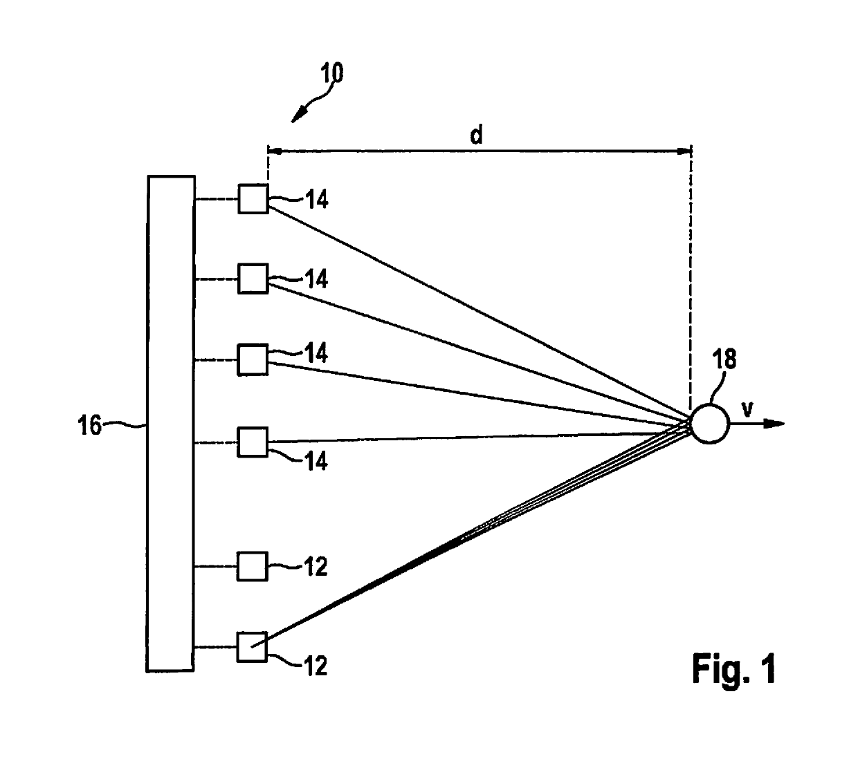
[0056]FIG. 1 is a diagram of a very simple example of a (MIMO) FMCW radar sensor 10 that in this example has only two transmitting antenna elements 12 and four receiving antenna elements 14. Larger numbers of antenna elements are possible in practice. Transmitting antenna elements 12 are powered by a control and evaluation unit 16 and emit radar signals that are reflected at an object 18 and received by each of the receiving antenna elements 14. Transmitting antenna elements 12 and receiving antenna elements 14 are each of similar construction and therefore have matching fields of view. The transmitting and receiving antenna elements can each be made up of a patch antenna array.

[0057]The received signals are mixed down to baseband signals and evaluated in control and evaluation unit 16. Radar sensor 10 is installed, for example, at the front in a motor vehicle and serves to measure distances d, angles, and relative velocities v of objects 18, for example of preceding vehicles. The f...


PUM


Abstract

A MIMO FMCW radar sensor and a MIMO time multiplexing method for localizing a radar target, in which an FMCW radar measurement is performed with a transmitted signal whose modulation pattern encompasses, for different transmission switching states that differ in terms of the selection of antenna elements used for transmission, mutually temporally interleaved sequences of ramps; ambiguous values for the relative velocity of the radar target are determined from a position of a peak in a two-dimensional spectrum; phase relationships between spectral values of spectra are checked for agreement with phase relationships expected for several of the determined values of the relative velocity; on the basis thereof, an estimated value for the relative velocity of the radar target is selected from the determined periodic values of the relative velocity; and the angle of the radar target is determined on the basis of amplitudes and / or phase relationships between obtained baseband signals.

Description

FIELD[0001]The present invention relates to a method for localizing a radar target with an angularly resolving MIMO FMCW radar sensor, in which received signals are mixed down with the transmitted signal to baseband signals, and the angle of a localized radar target is determined on the basis of amplitudes and / or phase relationships between baseband signals which are obtained for different selections of antenna elements of the radar sensor which are used for transmission and for reception.[0002]The present invention further relates to a radar sensor, in particular for motor vehicles, that is configured to carry out this method.BACKGROUND INFORMATION[0003]In motor vehicles, FMCW radar sensors are used to detect the traffic environment, in particular to localize other vehicles. The localization results can be used for a variety of assistance functions, for example for automatic separation control, automatic collision warning, or also automatic triggering of an emergency braking proced...

Claims


Application Information

Patent Timeline
Patent Type & Authority Patents(United States)
IPC IPC(8): G01S13/02G01S13/34G01S7/35G01S13/42G01S13/93G01S13/58G01S13/536G01S13/931
CPCG01S13/584G01S13/34G01S13/42G01S7/354G01S13/343G01S13/0209G01S13/931G01S13/536G01S2007/356G01S2013/0245G01S7/356
Inventor SCHOOR, MICHAELLOESCH, BENEDIKT
Owner ROBERT BOSCH GMBH
Why Eureka
Try Eureka