Light diffusing devices for use in photoimmunotherapy
a technology of light diffusion device and photoimmunotherapy, which is applied in the direction of therapy, instruments, fibre light guides, etc., can solve the problems of affecting the performance of the optical fiber, and affecting the effect of light diffusion
- Summary
- Abstract
- Description
- Claims
- Application Information
AI Technical Summary
Benefits of technology
Problems solved by technology
Method used
Image

Examples
example i
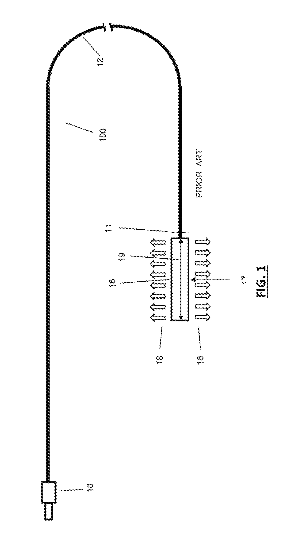
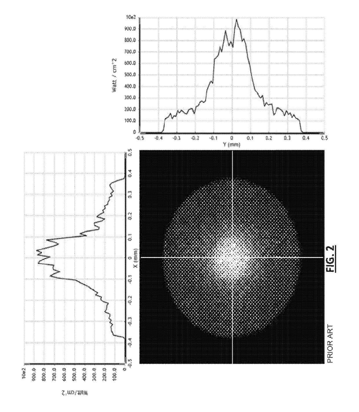
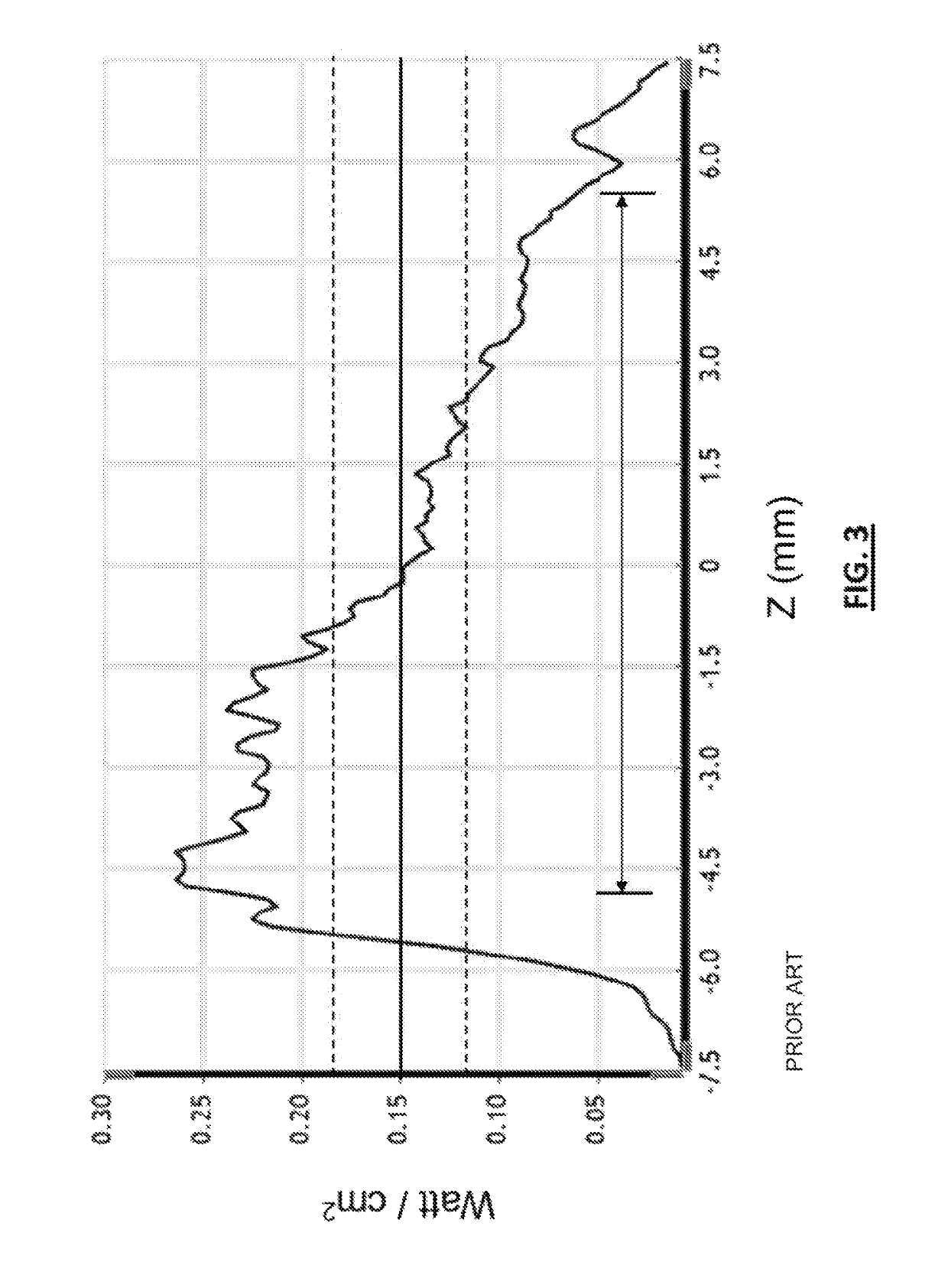
[0148]In one embodiment and referring to FIG. 31, a cylindrical light diffusing device 400 is provided wherein it (400) is exactly the same as the cylindrical light diffusing device 100 discussed above except that it (400) has the non-circular core fiber 302 instead of the conventional circular optical fiber 12 of the device 100. The vertical (i.e., latitudinal) cross-sectional view of the non-circular core fiber 302 is the same as the embodiment shown on FIG. 14. Using a 690 nm laser with 1 Watt launch power as the light source and adjusting the power until the irradiance measured at the center 17 of the longitudinal length of the diffuser 16 was 150 mW / cm2 resulted in the “top hat” core irradiance distribution shown in FIG. 32. The irradiance measurement value of 150 mW / cm2 is measured 0.75 mm from the central axis of the stated location of the diffuser 16. FIG. 32 shows the core irradiance distribution at the vertical cross-section (e.g., shown as “11” in FIG. 31) through the non...
example ii
[0149]In another embodiment of the present invention, a cylindrical light diffusing device is provided. This device has the same components as the device 400 discussed above in EXAMPLE I and shown in FIG. 31 except that the cylindrical diffuser 16 is now a conventional circular core optical fiber having a light emitting section containing internal scattering features 362 as shown in FIG. 33. FIG. 33 shows a vertical cross sectional view of this circular core fiber's 301 light emitting section having its cladding 352 and its circular fiber core 351, which contains internal scattering features 362. Using a 690 nm laser with 0.2 Watt launch power as the light source and adjusting the power until the irradiance measured at the center 17 of the longitudinal length of the circular core fiber's light diffusing section was 150 mW / cm2, this device resulted in the diffusing irradiance distribution shown in FIG. 34 which provides a generally “top hat” diffusing irradiance distribution. The irr...
example iii
[0152]In one exemplary embodiment of the device 300 and referring to FIGS. 9, 10, and 14, the device 300 includes the non-circular core fiber 302, the lead-in optical fiber 304, the at least one optical connector 306. During operation, the lead-in optical fiber 304 is in light communication to (i) a light source (not shown) and (ii) the non-circular core fiber 302 via the at least one optical connector 306. The lead-in fiber 304 has a 200 μm OD glass core and a 230 μm OD cladding. The length of the non-circular core fiber 302 is 30 cm, which distally terminates into the light blocking means 314 made out of a reflecting coating of aluminum deposition. During operation, the non-circular core fiber 302 is filled with laser light having an angular distribution of a NA of 0.22.
[0153]Referring FIGS. 10 and 14, the fiber core 350 of the non-circular core fiber 302 is constructed out of PMMA with a hexagonal geometry in a circumscribed ø660 μm diameter circle. The fiber core 350 is cladded ...
PUM
 Abstract
Description
Claims
Application Information
 - R&D
- Intellectual Property
- Life Sciences
- Materials
- Tech Scout
- Unparalleled Data Quality
- Higher Quality Content
- 60% Fewer Hallucinations
Browse by: Latest US Patents, China's latest patents, Technical Efficacy Thesaurus, Application Domain, Technology Topic, Popular Technical Reports.
© 2025 PatSnap. All rights reserved.Legal|Privacy policy|Modern Slavery Act Transparency Statement|Sitemap|About US| Contact US: help@patsnap.com