Nanoparticle production method, production device and automatic production device

a production method and nanoparticle technology, applied in the field of nanoparticle production methods, can solve the problems of difficult uniform particle size, small amount of substances, cruel cohesion, etc., and achieve the effects of high synthesis rate, high efficiency, and fast synthesis rate of nanoparticles

Active Publication Date: 2019-10-01
NIHON SUPERIOR CO LTD +1
View PDF22 Cites 0 Cited by
  • Summary
  • Abstract
  • Description
  • Claims
  • Application Information

AI Technical Summary

Benefits of technology

[0037]According to the first form of the present invention, since there is prepared the ingredient liquid for production of an nanoparticle that an ingredient material is mixed with a solvent, the solvent is a simple solvent that dissolves or disperses the ingredient material, and the following two cases are included that one is the case that the nanoparticles are synthesized from the ingredient materials in the solvent, and the other is the case that the solvent becomes a kind of liquid ingredient material and the nanoparticles are synthesized from a reaction between the solvent and the ingredient material. As an example of the former, when the solvent is water and the ingredient materials are nitric acid metal salt, organic matter and reducing agent, the nitric acid metal salt is reduced by the reducing agent so that an organic coated metal nanoparticle is synthesized. In addition, as an example of the latter, as shown in the patent document 2, when the solvent is alcohol and the ingredient material is silver carbonate, the alcohol acts as reducing agent and organic matter as well solvent, a silver nanoparticle generated from silver carbonate reduced by the alcohol is coated with the organic matter originated from the alcohol, so that a metal nanoparticle is generated. As thus, the present invention gives the liquid phase manufacturing process of a wide range of nanoparticle.
[0038]In addition, since disposing a reaction tube in which said ingredient liquid flows, filling said ingredient liquid and / or the same solvent as said ingredient liquid inside of said reaction tube, controlling a temperature of said solvent of said reaction tube at a synthesis temperature of said nanoparticle, supplying said ingredient liquid to an inflow end of said reaction tube, and mixing the supplied ingredient liquid with the solvent in the reaction tube, the solvent in the reaction tube is the same solvent as the solvent of the ingredient liquid, so that there is no problem as if the ingredient liquid is mixed with the solvent. In addition, when said ingredient liquid is filled in the interior of the reaction tube, the ingredient liquid can be stirred. Besides, because the solvent of the reaction tube and / or the ingredient liquid is done the temperature control (heating / warming / constant temperature / cooling are included) at the synthesis temperature, the ingredient liquid supplied changes in the state of reaction promptly and the synthesis of nanoparticles starts in the reaction tube. The higher the synthesis temperature is, the faster the synthesis rate of the nanoparticle is, and when the temperature of ingredient liquid is set at high temperature of the extent that synthesis does not start, the synthesis can be started as of the mixing promptly.
[0039]Furthermore, since the mixed liquid or the ingredient liquid is formed to the spiral flow streaming from said inflow end to the outflow end that goes around along a circumferential direction of the inner surface of the outer wall in said reaction tube, the ingredient liquid comes close to the inner surface of the outer wall in said reaction tube by the centrifugal force, and the heavy ingredient material also comes close to the inner surface of the outer wall in said reaction tube by the centrifugal force, so that the nanoparticle is easy to be synthesized near the inner surface of the outer wall. When disposing the temperature control means (heating device, warm temperature device, incubator and cooler etc. are included) same as the tape heater on the outer surface of the outer wall in said reaction tube, it is possible to synthesize the nanoparticle efficiently near the inner surface of the outer wall while controlling the temperature with high synthesis rate. In addition, since constructing the spiral flow, it is possible to adjust the time arriving from the inflow end to the outflow end, namely, the reaction time, and especially although depending upon the length of the reaction tube, it is possible to arrange variably the reaction time from several seconds to dozens of minutes by adjusting the pitch of the spiral flow (the distance advancing between one rotation). In addition, since the spiral flow is turbulent or a little turbulent, the nanoreaction is activated by increasing of the collision probability between particles, and the generation reaction of various nanoparticles can be realized with high efficiency. The present invention is completely different from the straight type of the laminar flow and the spiral tube type of the laminar flow as explained in the conventional embodiments.
[0040]Besides, by the amount that supplied ingredient liquid, the generation liquid is pushed out of the outflow end, and if the feed of the ingredient liquid is performed for continuity, it is advantageous in that the generation liquid can be also refined for continuity and it is possible to realize the mass synthesis of nanoparticles.
[0041]According to the second form of the present invention, said reaction tube is divided into one or more partitions along a streaming direction of said ingredient liquid, in an inlet side of said partition there is formed an annular opening portion which is opened in a circumferential direction along said inner surface of said outer wall, said spiral flow passes through said annular opening portion, so that an annular spiral flow streams through one or more partitions, and hence although the ingredient liquid and the solvent of the reaction tube partially mix each other in the input side of first partition, most of ingredient liquid passes through said annular opening portion and flows into first partition, and while taking a step that it flows in from next annular opening portion to second partition, the ingredient liquid becoming the annular spiral flow goes to the outflow end from last partition. Therefore, synthesis of nanoparticle occurs in the continuous annular spiral flow with comparatively thin thickness, so that the diffusion of ingredient liquid can be suppressed and the nanoparticle can be generated approximately according to the concentration of ingredient liquid.
[0042]In addition, after it passes the first annular opening, the spiral flow stays temporarily in first partition while rotating, and after it passes next annular opening, the spiral flow stays temporarily in next partition while rotating, so that the residence time in the reaction tube gets longer than the spiral flow without the partition, and the generation reaction time of nanoparticles gets possible to be extended still more. Therefore, the reaction time becomes to be shortest in the case that there is no partition completely, and the increase of the installation number of partition gets possible to set the generation reaction time for the longer time.

Problems solved by technology

Since nanoparticles are produced by melting a solid in the solid phase method, a large quantity of nanoparticles can be obtained because of a large amount of material, but there are many cases that the particle size becomes large, the cohesion is cruel and the uniformity of particle size is difficult.
Since nanoparticles are produced by means of gaseous reaction in the gas phase method, an amount of substance becomes small, and it is not suitable for a large amount production of nanoparticles.
However, there are weak points that the mass production of nanoparticles is difficult because the collision probability becomes small in the laminar flow state and the control of the production apparatus is difficult because nanoparticles are manufactured in an extremely short time of 1-60 seconds.
Therefore, the mass production of nanoparticles is unsuitable and the difficulty of generation control exists as a weak point.

Method used


Image

  • Nanoparticle production method, production device and automatic production device
  • Nanoparticle production method, production device and automatic production device
  • Nanoparticle production method, production device and automatic production device

Examples


first example

The First Example

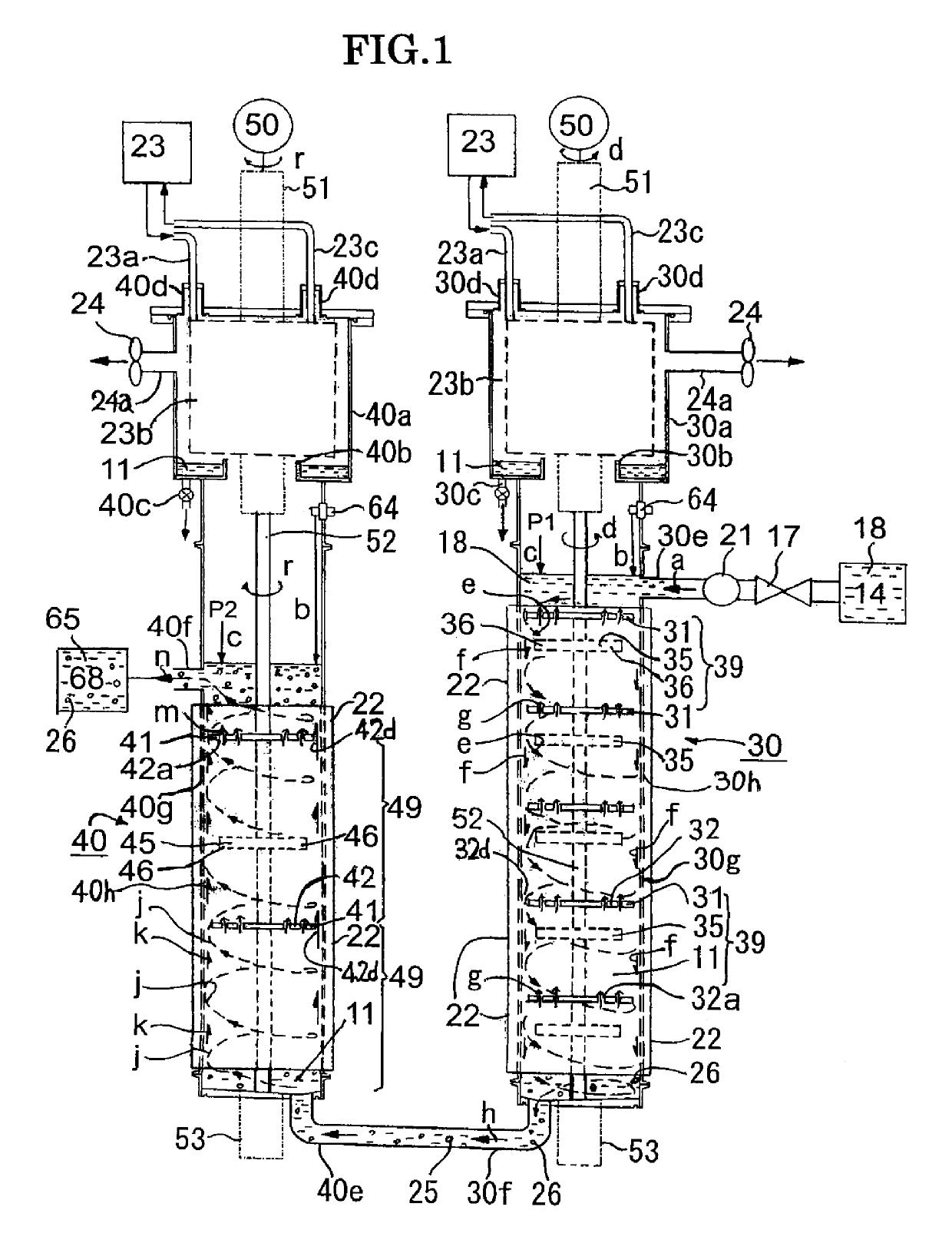
[0090]FIG. 1 is a front diagram of the first example of the nanoparticle production apparatus concerning the present invention, and the series type nanoparticle production apparatus of the first reaction tube (fall flow) and the second reaction tube (lift flow) is shown. In the following explanation, after explaining the outline regarding to the construction of the first example, the function of each member is explained along the streaming process of the ingredient liquid 18 in the ingredient liquid retention tank 14. In addition, in the first reaction tube 30 and the second reaction tube 40, the same code is referred to the same member or the member having a similar function and its description is omitted partly. In addition, the nanoparticle includes not only the nanoparticle without the organic coating layer but also the composite nanometal particle with the organic coating layer formed around the metal core, and the composite nanometal particle is simply called ...

second example

The Second Example

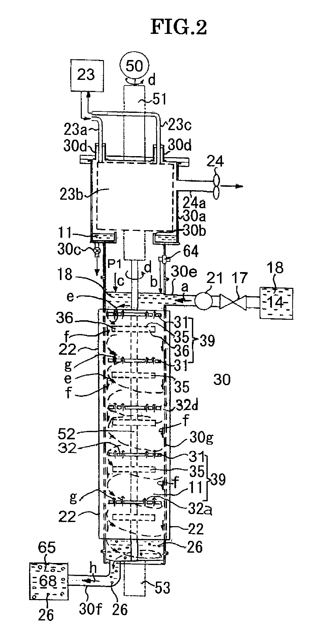
[0100]FIG. 2 is a front diagram of the second example of the nanoparticle production apparatus concerning the present invention, and the nanoparticle production apparatus of single reaction tube (fall flow) is shown. In the second example, the reaction rube is composed of only the first reaction tube 30 which is shown in FIG. 1, and a difference with the first example is that the generation liquid retention tank 68 is connected to the outflow end 30f and the generation liquid 65 is saved. Therefore, the same code is referred to the same member, and as far as there is not special dissimilarity, the detailed description is omitted.

[0101]In the second example of FIG. 2, the reaction of the ingredient material and the solvent 11 in the ingredient liquid 18 is completed or approximately completed in the first reaction tube 30, and the nanoparticle 26 is generated. The reaction time can be appropriately arranged based upon adjusting of the supply flow rate of ingredient ...

third example

The Third Example

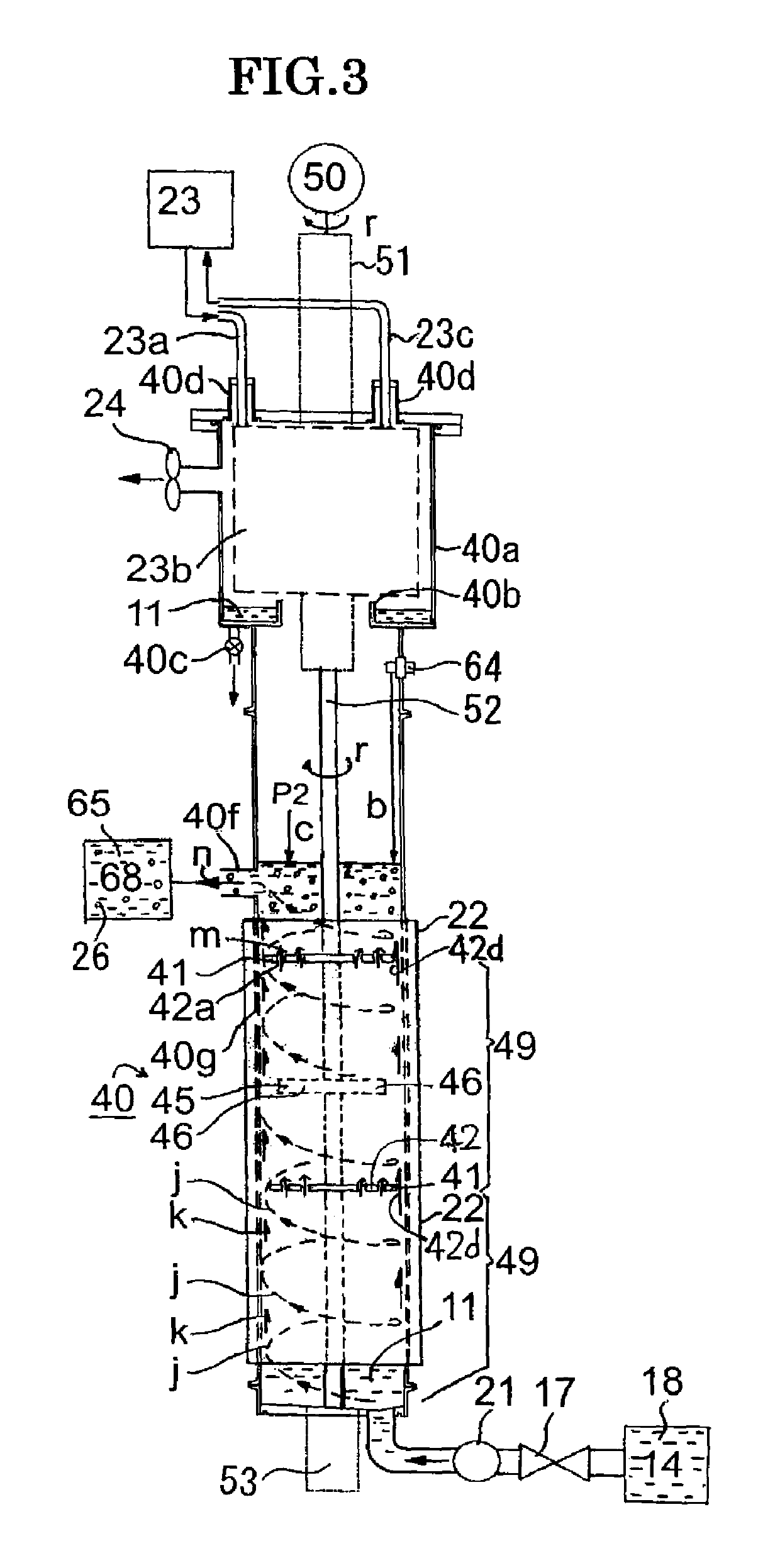
[0102]FIG. 3 is a front diagram of the third example of the nanoparticle production apparatus concerning the present invention, and the nanoparticle production apparatus of single reaction tube (lift flow) is shown. In the third example, the reaction rube is composed of only the second reaction tube 40 which is shown in FIG. 1, and a difference with the first example is that the ingredient liquid retention tank 14 is connected to the bottom face of the second reaction tube 40 through the electromagnetic valve 17 and the pump 21 and the ingredient liquid 18 is supplied from this ingredient liquid retention tank 14 and from the lower portion of the second reaction tube 40. In the same manner, the same code is referred to the same member, and the detailed description is omitted.

[0103]In the third example of FIG. 3, the ingredient liquid 18 is directly supplied to the second reaction tube 40, and although the lift flow k (called the lift annular spiral flow, too) is for...


PUM

PropertyMeasurementUnit
diameteraaaaaaaaaa
diameteraaaaaaaaaa
temperatureaaaaaaaaaa

Abstract

A nanoparticle production apparatus and automatic production apparatus that allow continuous mass production of nanoparticles with a uniform particle diameter and allow freely adjusting the generation time are provided. This nanoparticle production apparatus is characterized by being configured from: reaction tubes (30, 40) which are filled with the same solvent (11) as that in a ingredient liquid (18), which is used in nanoparticle production and comprises an ingredient material (12) mixed into the solvent (11); a heating apparatus (22) which controls the temperature of the solvent (11) in the reaction tubes (30, 40) to the synthesis temperature of the nanoparticles (26); inflow ends (30e, 40e) of the reaction tubes into which the ingredient liquid (18) is supplied; rotors (35, 45) which form spiral flows (e, j) along the inner surface of the outer walls (30h, 40h) of the reaction tubes while mixing the ingredient liquid (18) supplied and the solvent (11) present in the reaction tubes (30, 40); and outflow ends (30f, 40f) of the reaction tubes (30, 40) for forming, in the spiral flows (e, j), nanoparticles (26) from the ingredient material (12) and discharging a generation liquid (65) containing the nanoparticles (26).

Description

CROSS REFERENCE TO RELATED APPLICATIONS[0001]This application is a national stage of international application PCT / JP2013 / 068978, filed on Jul. 11, 2013 which is incorporated herein by reference.FIELD OF THE INVENTION[0002]The present invention relates to a method producing nanoparticles from a solvent an ingredient material, and more specifically relates to a production method of nanoparticles with an uniform thin diameter, a production device and an automatic production device.BACKGROUND ART[0003]In late years, as a metal nanoparticle for junction use or metal pattern formation, there has been done the development of the composite nanometal particle that the organic coating layer comprising various kinds of organic substance surrounds the metal core of less than or equal to 100 nm. By way of example only, in example 1 of Japanese Patent Laid-Open No. 10-183207 (Patent Document 1), it is described the ultrafine particle having the organic coating layer of stearic acid surrounding t...

Claims


Application Information

Patent Timeline
Patent Type & Authority Patents(United States)
IPC IPC(8): B22F9/24B22F1/00B22F9/02B82Y30/00B82Y40/00B22F1/054
CPCB22F9/02B22F9/24B22F1/0044B22F1/0018B22F2301/255B82Y40/00B82Y30/00B22F3/003B22F2998/10B22F2304/05B22F2999/00B22F2009/245B22F1/054B22F1/056B22F1/07
Inventor KOMATSU, TERUONISHIMURA, TETSURO
Owner NIHON SUPERIOR CO LTD
Why Eureka
Try Eureka