
Anchoring a joining element in an object

a technology of joining elements and objects, applied in the field of mechanical engineering and construction, can solve the problems of insufficient stability, hard or impossible to properly introduce the male parts, and the joints between different parts are difficult to achieve, and achieve the effect of facilitating injection molding of liquefiable parts and enhancing strength

Active Publication Date: 2019-10-01
WOODWELDING +1
View PDF12 Cites 2 Cited by
  • Summary
  • Abstract
  • Description
  • Claims
  • Application Information

AI Technical Summary

Benefits of technology

The patent describes a method for joining two parts together using a tool that applies pressure and vibration. The tool is pressed against the outer surface of the part to create a joint. The part also has grooves on its surface that help with strength. The grooves are arranged in a staggered way, similar to a T-bar design, to increase strength in the direction parallel to the grooves. This method helps create a strong bond between the parts without causing any deformation of the surface.

Problems solved by technology

Joints between different parts are an important issue in mechanical construction, for example in the furniture industry.
In the system of WO 2013 / 104422, if the grooves of the male and female parts do not match each other with sufficient accuracy, it will be either hard or impossible to introduce the male part properly, or the effect of pressing the furniture parts toward each other is not achieved and, consequently, sufficient stability is not achieved.
A further important issue in connection to joints for furniture or other objects is manufacturing cost, both for the manufacturing of the joining elements and for the act of providing the parts with the joining elements.
While joining elements of metal, for example with a threaded anchored portion, can be designed so that the shape of the head portion sufficiently satisfies the requirements for their stability, their manufacturing is comparably expensive.
Also, if the anchoring in the respective parts is done in the factory (as opposed to self-assembly by the customer), it is comparably time-consuming and thus expensive.
However, this kind of anchoring features the disadvantage that the glue volume has to be adapted to the porosity of the chipboard.
If too little is injected, the interface lacks sufficient glue because the glue will be soaked into the wood, and if too much is injected, a liquid cushion will arise that may prevent exact depth positioning of the joining element.
Also, gluing entails cleaning efforts, and the step of gluing is comparably time consuming in that the glue has to harden for some time.
Even if the glue is very strong, the glue connection will provide a limited anchoring stability if one of the parts itself has a material of limited stability, for example if the part is of a comparably brittle chipboard.
While both these methods result in an improved in-depth anchoring of the joining element compared to glue connections and can be applied with a rather high precision of placement and relatively quickly, they entail energy input and considerable force on the rear (proximal) end of the joining element, which in combination may lead to deformations of the protruding (head) portion.
They thus are not as such suitable for anchoring joining elements of liquefiable material the head portion of which must have a pre-defined shape and position.

Method used


Image

  • Anchoring a joining element in an object
  • Anchoring a joining element in an object
  • Anchoring a joining element in an object

Examples


Embodiment Construction

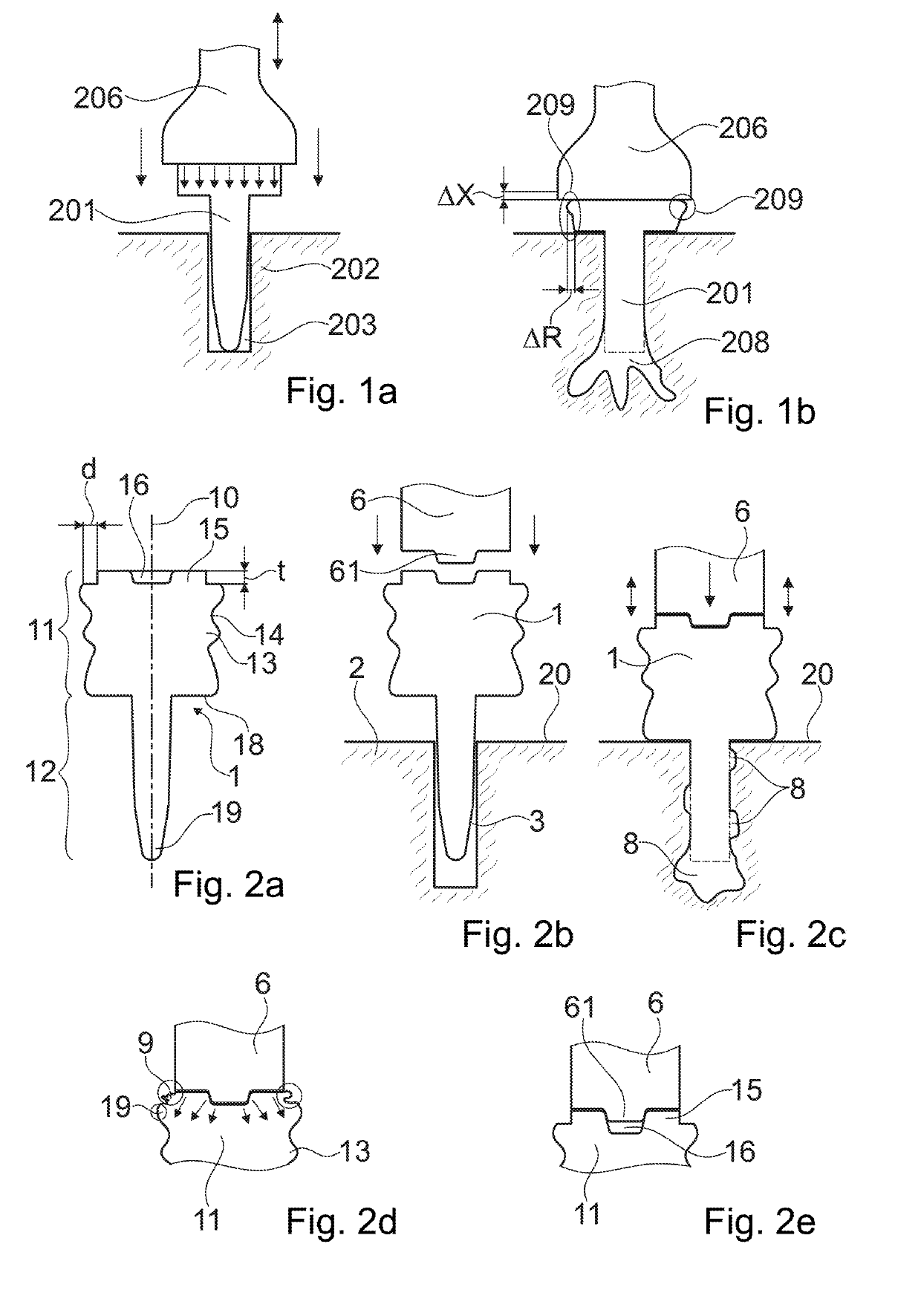
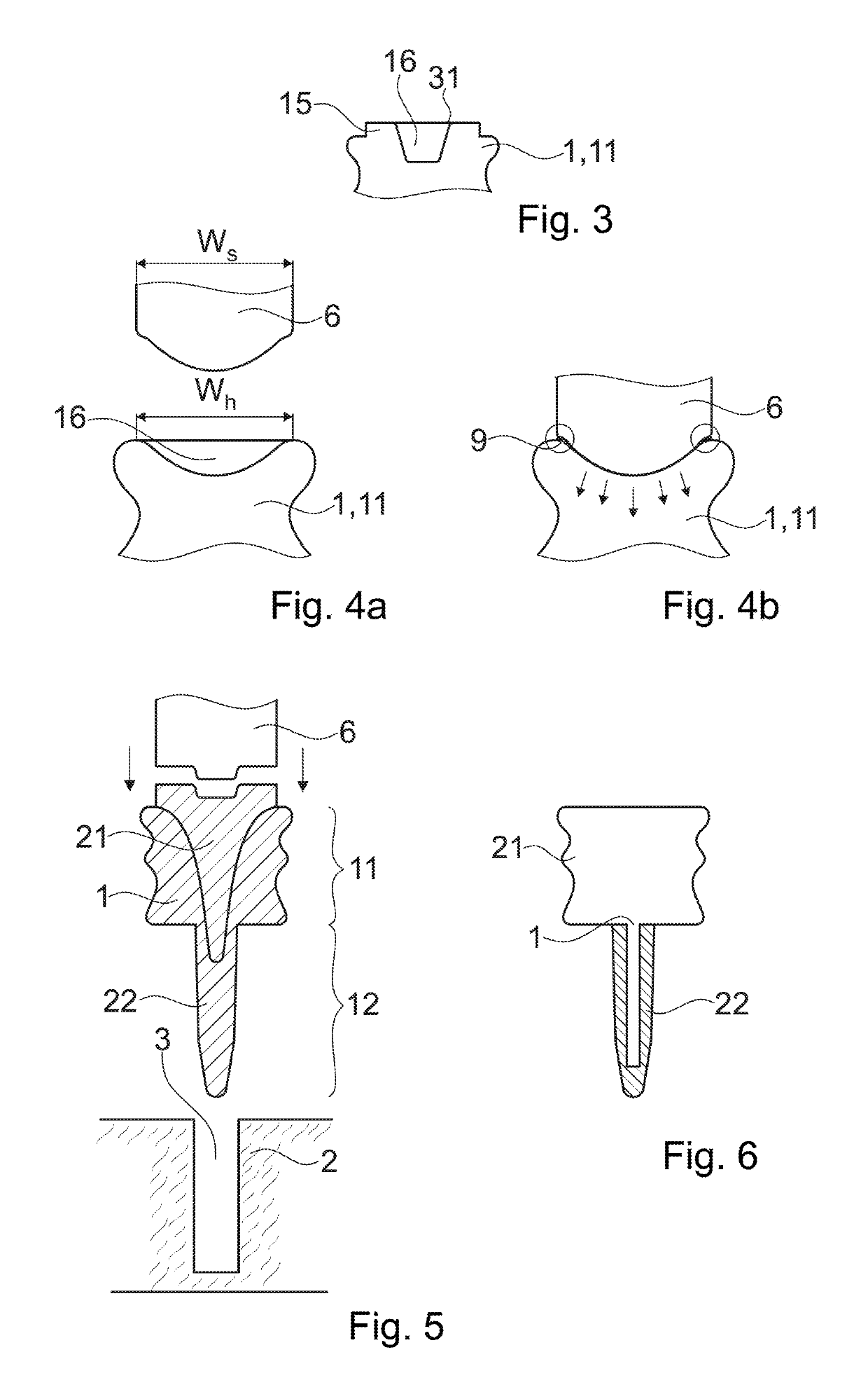
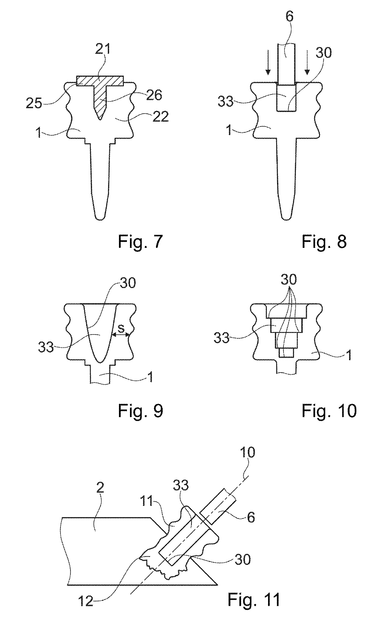
[0163]A joining element 1 as illustrated in FIG. 2a includes a head portion 11 and an anchoring portion 12. Between the head portion and the anchoring portion, a distally facing shoulder 18 is formed, which shoulder serves as stop face in the anchoring process described hereinafter.

[0164]The joining element 1 may be essentially symmetric with respect to a rotation around its axis 10, with the possible exception of energy concentrating elements (not shown in FIG. 2a), such ribs or humps, of an outer surface of the anchoring portion 12.

[0165]The head portion 11 has a lateral outer surface that is shaped to engage into a corresponding structure of a female part of a further object so that the object into which the joining element is anchored and the further object may be assembled to one another. Especially, the lateral outer surface has a structure 13 that makes a positive-fit connection with the female part possible, in a manner that forces in axial directions (with respect to the ax...


PUM

PropertyMeasurementUnit
aspect ratioaaaaaaaaaa
frequencyaaaaaaaaaa
frequencyaaaaaaaaaa

Abstract

A joining element has an anchoring portion for in-depth anchoring in the object and a head portion arranged proximally of the anchoring portion with respect to an insertion axis. The head portion has a lateral outer surface that has a structure that is well-defined, especially within tight tolerances. The joining element is positioned relative to an object of a non-liquefiable material such that the anchoring portion reaches into an opening of the object or is placed adjacent a mouth thereof. Then, the joining element is pressed towards a distal direction, to press the anchoring portion into the opening, while mechanical vibration energy is coupled into the joining element by a tool, in an amount and for a time sufficient for liquefaction of a portion of the thermoplastic material to cause interpenetration of the thermoplastic material into structures of the object.

Description

BACKGROUND OF THE INVENTIONField of the Invention[0001]The invention is in the field of mechanical engineering and construction and especially furniture construction. In particular, it relates to a method of anchoring a joining element in an object and to an according joining element, as well as to an assembly including such a joining element.Description of Related Art[0002]Joints between different parts are an important issue in mechanical construction, for example in the furniture industry. Many of such joints comprise, on at least one of the parts to be joined, a joining element with an in-depth anchored portion (“anchoring portion” in the following text) and a protruding portion, often referred to as “head”. The in-depth anchored portion may for example be screwed into the part, and the head may include means for making the connection to the further part possible. To this end, the further part may include a second joining element cooperating with the joining element of the first...

Claims


Application Information

Patent Timeline
Patent Type & Authority Patents(United States)
IPC IPC(8): B32B37/00B29C65/00B29C65/60B29C65/56B29C65/78B29C65/64B29C65/08B29K101/12
CPCB29C65/7844B29C65/565B29C66/30325B29C65/609B29C65/08B29C66/9261B29C65/603B29C65/645B29C66/7487B29C66/727B29C65/7808B29C66/9231B29C66/81429B29C66/74B29C66/8145B29C66/30321B29C66/3032B29C66/7392B29C66/474B29K2071/00B29K2025/06B29K2023/12B29K2077/00B29K2055/02B29K2081/04B29K2069/00B29C66/71B29K2079/085B29K2027/06B29C66/73161B29K2023/06B29K2025/08B29K2067/00B29K2101/12B29K2059/00B29K2081/06B29C66/872B29L2031/44
Inventor DIZDAR, NIHATKÄLL, HÅKANHÅKANSSON, PONTUSSANKARAN, MUTHUMARIAPPANLEHMANN, MARIOMAYER, JÖRGTORRIANI, LAURENTAESCHLIMANN, MARCEL
Owner WOODWELDING
Learn More