Methods and systems for detection of non-volatile solutes

a non-volatile solute and detection method technology, applied in the field of non-volatile solute detection methods and systems, can solve the problems of non-linear calibration curves of aerosol detectors, solvent gradient lc separation is often considered to be the single most significant limitation of lc-aerosol detectors, and the non-linear response is commonly viewed as the single most significant limitation of aerosol detectors, so as to prevent the supersaturation of volatile components, the effect of minimizing

Active Publication Date: 2019-10-01
DIONEX CORP
View PDF24 Cites 2 Cited by
  • Summary
  • Abstract
  • Description
  • Claims
  • Application Information

AI Technical Summary

Benefits of technology

[0016]Based on the inventor's new insight, as described above, the present teachings provide new CAD instrument design concepts to minimize the contribution, to the CAD signal, of dried particles for which Dp≤10 nm. Implementation of the new design concepts can provide an instrument response that approaches a ⅓ power law response over a wider dynamic range than is currently achieved. The new designs can thus provide a wider linear dynamic range (when the instantaneous signal is raised to the third power). Achieving this goal would thereby remove or greatly minimize a major limitation to the usefulness of CAD.
[0021]Various embodiments of apparatuses, systems and methods in accordance with the present teachings may address or implement the above-noted process (3), in part, by configuring a spray chamber of a CAD system with an internal chamber shape such that the largest droplets (which are incapable of complete solvent evaporation during transport through the system) are directed along a first path that leads to a waste port whereas smaller droplets are directed along a second path, divergent from the first path, that leads to a particle charging chamber, wherein the walls of the spray chamber are oriented so as to minimize breaking apart of droplets upon impact with the walls. The above-noted process (3) may be further addressed or implemented, in part, by configuring the CAD system such that a transport conduit provides a straight flow path or only low angle bends where the radius of curvature of the bend is at least 5 (five) times the cylindrical tube radius of the transport conduit (e.g., Pui, D. Y. H. et al. “Experimental Study of Particle Deposition in Bends of Circular Cross Section”, Aerosol Science and Technology, 7:3, 1987, pp. 301-315) between the spray chamber and the downstream charging chamber such that impact of droplets against the walls of the transport conduit is minimized.
[0024]In accordance with some embodiments, additional design features may be provided so as to address the above described limitation of CAD with respect to solvent dependency of response. As discussed above, changes in response during solvent gradient LC separations are mainly attributed to changes in solvent properties that affect primary aerosol characteristics, transport and evaporation. Accordingly, an embodiment may include real time adjustment of nebulizing gas flow according to changes in solvent properties so as to minimize changes in primary aerosol characteristics. In this regard, nebulizing gas flow adjustments may be pre-programmed based on prior knowledge of solvent properties such as viscosity, surface tension and density and using experimentally determined relationships between such properties and experimental results or, possibly, predictive models of nebulization. Furthermore, sheath gas flow may also be adjusted in real time so as to maintain a constant combined gas flow, comprised of nebulizing and sheath gas flows, so as to also minimize changes in aerosol transport and evaporation that may result from solvent gradients.
[0025]An important consideration is solvent load especially for water since, except for very low liquid flow rates, the aerosol is expected to be supersaturated with water vapor. As discussed above, under most LC conditions, some of the largest droplets must be removed to allow complete solvent evaporation. Nonetheless, even with the largest droplets removed, some solvent compositions may be such that, under the prevailing gas flow rates, some of the largest remaining droplets may fail to completely evaporate in the time available between droplet generation and introduction of the gas and particle stream into a downstream particle charging chamber. Evaporation temperature setting is one parameter that can effect evaporation time. Accordingly, some embodiments in accordance with the present teachings may include variable temperature control within the spray chamber or within a transport conduit fluidically coupled between the spray chamber and a particle charging chamber. The temperature adjustments, which may be automatically controlled, may be caused to vary in accordance with a measured or predicted varying vapor pressure, within the spray chamber, of a solvent component. Alternatively or additionally, some embodiments in accordance with the present teachings may include a liquid flow splitter (such as valve or T-junction) fluidically coupled between the source of the varying composition liquid (e.g., a chromatographic column) and the spray chamber, such that the splitter only admits a limited flow rate of liquid into the spray emitter such that the interior of the spray chamber never becomes supersaturated in any volatile component. Experiments performed by the inventor have indicated that a liquid flow split is necessary, in practice, to allow normalization of response for different solvents. Other alternative embodiments may include use of a single nebulizer-to-sheath flow ratio setting and real time adjustment of nebulizer and sheath gas flows during a run such that the total gas flow is sufficient to prevent supersaturation of any volatile component within the spray chamber.

Problems solved by technology

7418-7427) state that “A significant barrier to the implementation of the aerosol detectors has been that they exhibit non-linear calibration curves.” Combination of Eq.
Such non-linear response is commonly viewed as the single most significant limitation of LC-aerosol detectors.
Further, solvent dependency of response during solvent gradient LC separations is often considered to be an almost equally significant limitation.

Method used


Image

  • Methods and systems for detection of non-volatile solutes
  • Methods and systems for detection of non-volatile solutes
  • Methods and systems for detection of non-volatile solutes

Examples


Embodiment Construction

[0040]The following description is presented to enable any person skilled in the art to make and use the invention, and is provided in the context of a particular application and its requirements. Various modifications to the described embodiments will be readily apparent to those skilled in the art and the generic principles herein may be applied to other embodiments. Thus, the present invention is not intended to be limited to the embodiments and examples shown but is to be accorded the widest possible scope in accordance with the features and principles shown and described. The particular features and advantages of the invention will become more apparent with reference to the appended FIGS. 1-3, 4A, 4B, and 5-8, 9A and 9B taken in conjunction with the following description.

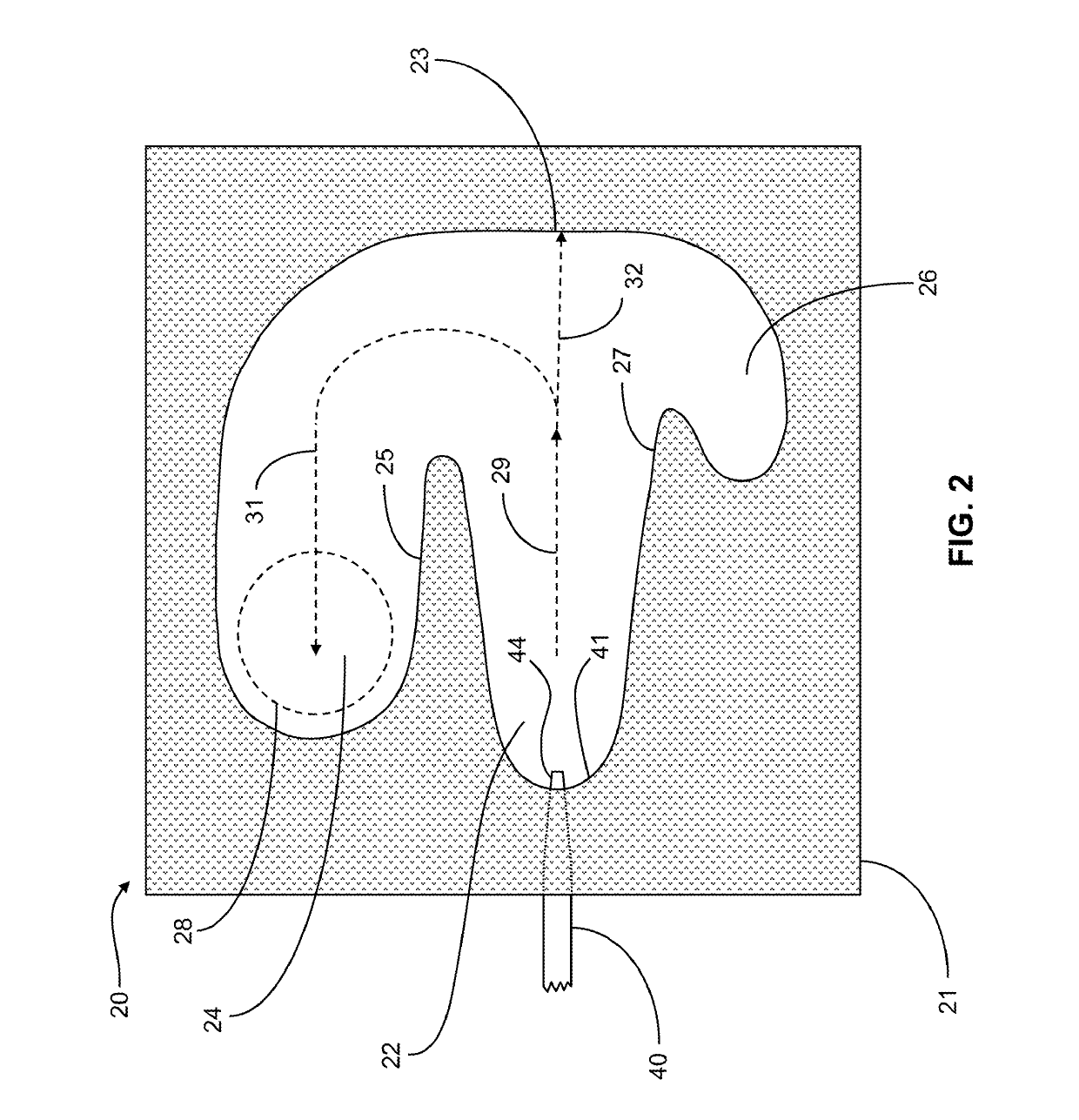
[0041]FIG. 2 depicts a cross-sectional view through a nebulizer constructed in accordance with an embodiment of an invention taught in co-pending U.S. patent application Ser. No. 14 / 288,693, which is assigned t...


PUM

PropertyMeasurementUnit
particle diametersaaaaaaaaaa
diametersaaaaaaaaaa
diameteraaaaaaaaaa

Abstract

A system for detection of non-volatile solutes dissolved in solution comprises: a spray emitter system configured to receive a flow of the solution and generate an aerosol comprising droplets thereof, the generated droplets comprising a restricted size range; a spray chamber configured to receive the aerosol and emit a modified aerosol comprising droplets having a diameter smaller than a predetermined value; a conduit configured to receive a flow of the modified aerosol and to evaporate the solvent so as to generate an aerosol comprising solid particles of the solutes; a charging chamber configured to receive the aerosol and impart electric charge to the solid particles; and a detector configured to measure a quantity of charge imparted to the solid particles, wherein the restricted size range is such that solid particles having diameters greater than 10 nm comprise a substantial portion of all particles received by the charging chamber.

Description

CROSS REFERENCE TO RELATED APPLICATIONS[0001]This application claims priority to U.S. Provisional Application No. 62 / 183,621 titled “Methods and Systems for Detection of Non-Volatile Solutes” and filed on Jun. 23, 2015 and, further, is related to commonly-assigned co-pending U.S. patent application Ser. No. 14 / 288,693, filed May 28, 2014 and titled “Nebulizer for Charged Aerosol Detection (CAD) System”, said applications hereby incorporated by reference herein in their entirety.FIELD OF THE INVENTION[0002]The present invention relates to devices for detecting and quantifying components of a liquid sample stream.BACKGROUND OF THE INVENTION[0003]Charged aerosol detection is a popular and valuable technique for the detection and quantification of substances present in a liquid sample stream, and is particularly well-suited to use in connection with liquid chromatography applications. Briefly described, a charged aerosol detection (CAD) system consists of a nebulizer for generating a sp...

Claims


Application Information

Patent Timeline
Patent Type & Authority Patents(United States)
IPC IPC(8): G01N30/34G01N30/88
CPCG01N30/88G01N30/34
Inventor GAMACHE, PAUL H.
Owner DIONEX CORP
Why Eureka
Try Eureka