Calibration device, calibration method, and computer readable medium for visual sensor

a technology of visual sensor and calibration method, applied in image analysis, image enhancement, program-controlled manipulators, etc., can solve the problems of consuming unnecessary time to reduce efficiency, affecting the operability of an operator, and distorted shape of a target mark appearing in the camera

Active Publication Date: 2019-10-08
FANUC LTD
View PDF26 Cites 2 Cited by
  • Summary
  • Abstract
  • Description
  • Claims
  • Application Information

AI Technical Summary

Benefits of technology

[0010]If the shapes of the target mark appearing in the multiple cameras are distorted in different ways, a model pattern generated by using one camera is often prohibited from being applied to a different camera. Hence, if the shapes of the target mark appearing in the cameras are distorted in different ways, a model pattern should be generated for each of the multiple cameras. Further, to allow detection of the target mark, a parameter for detecting the target mark should be set for each of the multiple cameras such as exposure time, a calibration range in an image, a shape model about the target mark, or a detection parameter, for example. However, generating a model pattern and setting a parameter for detection for each of the multiple cameras during implementation of calibration largely affects the operability of an operator and consumes unnecessary time to decrease efficiency. Hence, in the case of calibration on the multiple cameras, eliminating the need to set a parameter for each of the cameras repeatedly has been required during implementation of calibration.
[0012]The present invention provides a calibration device, a calibration method, and a program capable of eliminating the need to generate a model pattern and set a parameter for detecting a target mark repeatedly for each of multiple cameras while a stereo camera with these cameras is calibrated.
[0023]A calibration device, a calibration method, and a program provided by the present invention are capable of eliminating the need to generate a model pattern and set a parameter for detecting a target mark repeatedly for each of multiple cameras while a stereo camera with these cameras is calibrated.

Problems solved by technology

However, the multiple cameras are attached at separate positions, so that the shapes of a target mark appearing in the cameras are distorted in different ways.
However, generating a model pattern and setting a parameter for detection for each of the multiple cameras during implementation of calibration largely affects the operability of an operator and consumes unnecessary time to decrease efficiency.

Method used


Image

  • Calibration device, calibration method, and computer readable medium for visual sensor
  • Calibration device, calibration method, and computer readable medium for visual sensor
  • Calibration device, calibration method, and computer readable medium for visual sensor

Examples


Embodiment Construction

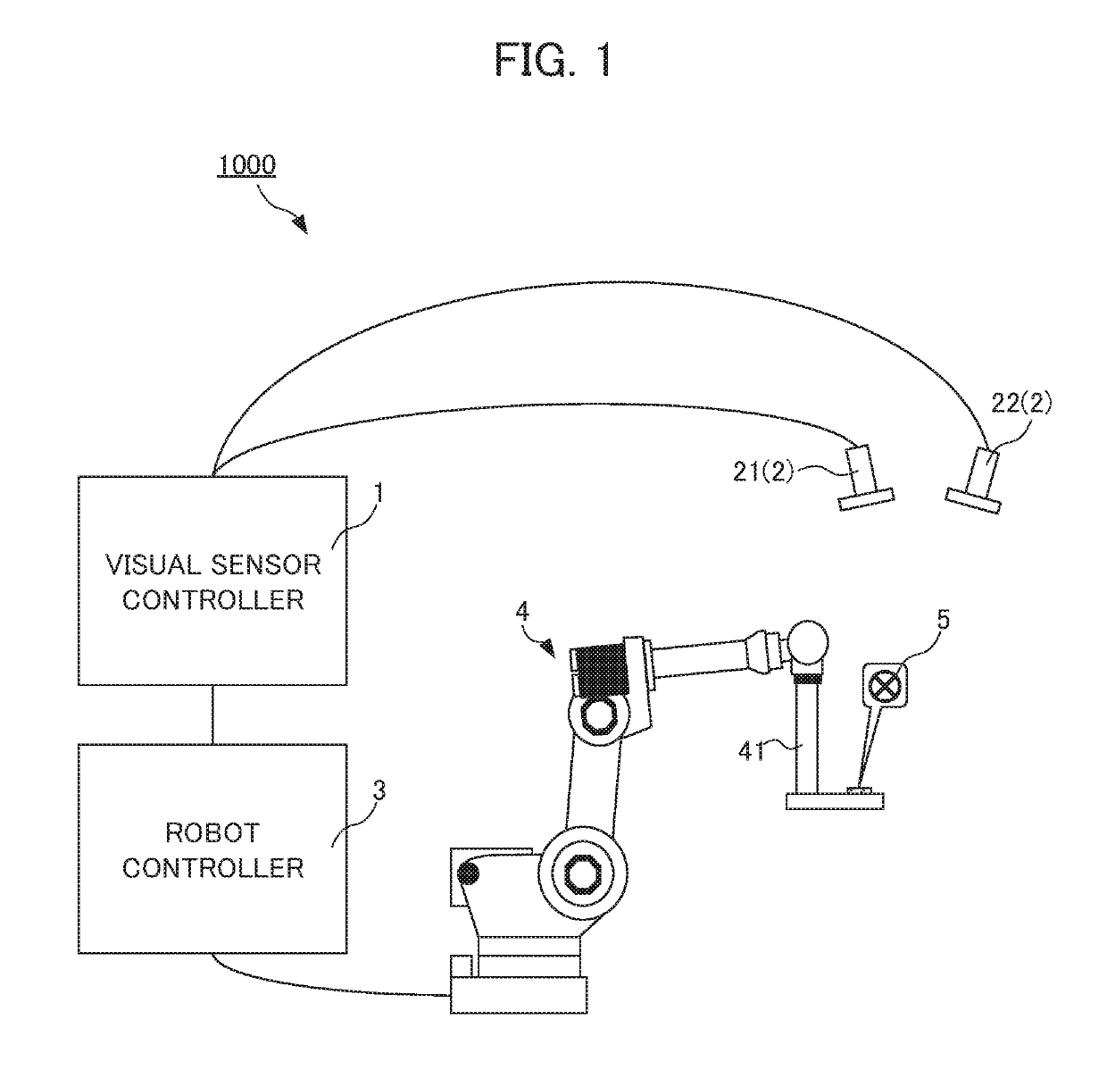
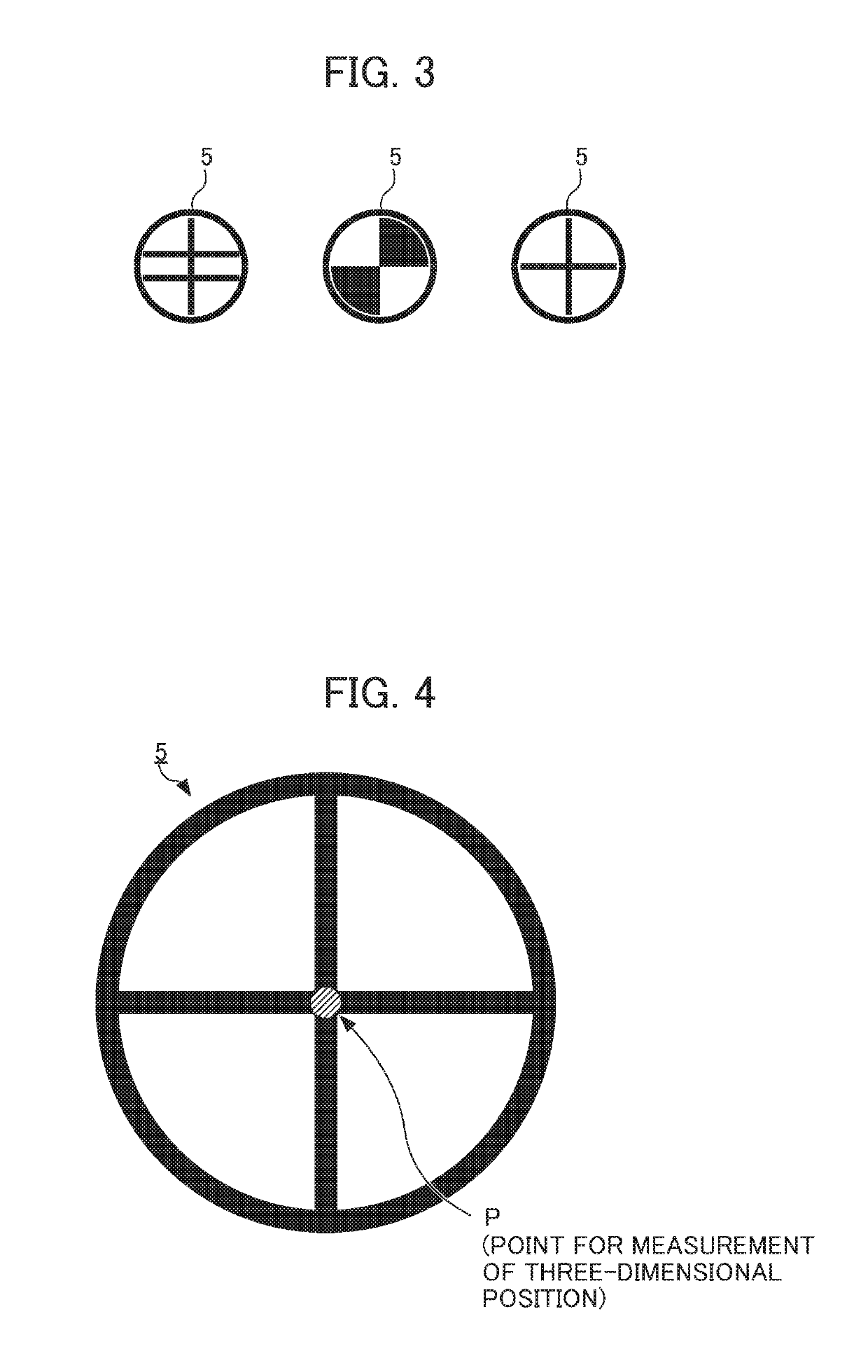
[0039]An example of an embodiment of the present invention will be described below. In this embodiment, a visual sensor controller is described as an example of a calibration device. FIG. 1 shows the configuration of a robot system 1000 entire for performing calibration on a visual sensor, particularly calibration by using a stereo camera with multiple cameras. As shown in FIG. 1, the robot system 1000 includes: the stereo camera 2 with two cameras (a first camera 21 and a second camera 22); a visual sensor controller 1 (as a calibration device) that makes three-dimensional measurement through image processing on data about an image captured by the stereo camera 2; a robot 4 having an arm 41 with an end portion to which a target mark 5 is attached; and a robot controller 3 for control over the robot 4. The number of cameras forming the stereo camera 2 is not limited to two but can be any number of two or more. Each of the cameras forming the stereo camera 2 is certainly applicable a...


PUM


Abstract

A parameter for detecting a target mark 5 is not required to be set for each camera repeatedly while a stereo camera 2 is calibrated. A calibration device 1 associates position information in an image coordinate system at a first camera 21 of a stereo camera 2, position information in an image coordinate system at a second camera 22 of the stereo camera 2, and position information in a robot coordinate system at a robot 4. The calibration device comprises: first parameter setting unit 102 that sets a first parameter for detecting a target mark 5 attached to the robot 4 from data about an image captured by the first camera 21; and a second parameter setting unit 104 that sets a second parameter for detecting the target mark 5 from data about an image captured by the second camera 22 based on the first parameter.

Description

[0001]This application is based on and claims the benefit of priority from Japanese Patent Application No. 2017-00664, filed on 12 Jan. 2017, the content of which is incorporated herein by reference.BACKGROUND OF THE INVENTIONField of the Invention[0002]The present invention relates to calibration on a visual sensor, particularly, to a calibration device, a calibration method, and computer readable medium encoded with a program for detecting a target mark during implementation of calibration using a stereo camera with multiple cameras.Related Art[0003]In a robot system, a robot is given a visual function. Operation such as handling or machining on a work is done by making the robot recognize the position of a subject. This visual function is fulfilled by capturing an image of the subject with a visual sensor attached to a hand or a neighboring part of the robot or a visual sensor provided around the robot. In such a robot system, to acquire the position information of the subject vi...

Claims


Application Information

Patent Timeline
Patent Type & Authority Patents(United States)
IPC IPC(8): B25J9/16G06T7/80B25J19/04
CPCG06T7/85B25J9/1692B25J9/163B25J9/1697B25J19/04G06T2207/30204G06T2207/10012B25J9/1653B25J9/1671B25J19/023
Inventor NAMIKI, YUUTAWARASHINA, FUMIKAZU
Owner FANUC LTD
Why Eureka
Try Eureka